User Tools
Site Tools
LCD module data
Numeric
Character
Mixed
- ≡ Uniden FP203 ✘
- ≡ Uniden FP204 ✘
- ≡ VIP89Z G-Code ✘
Graphic
key: ≡ parallel, ↔ serial, ~ LVDS, _ unknown, ✘ discarded as not useful
| LCD Description | |
|---|---|
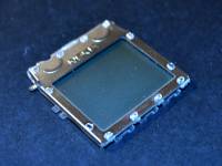
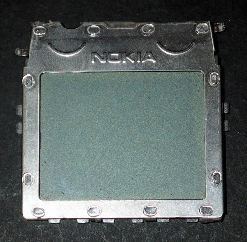
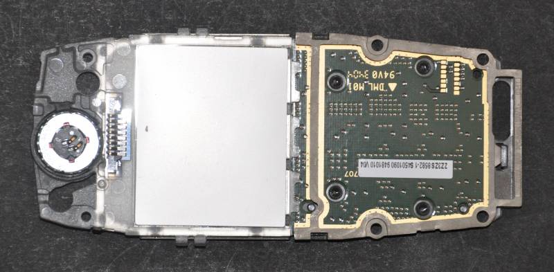
| Model | Nokia 2280 |
| Manufacturer | |
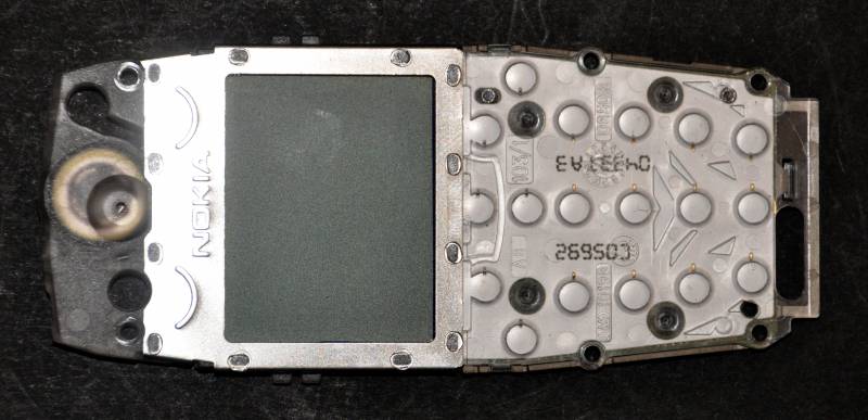
| Recovered from | Nokia 2280 cellphone |
| Board IDs | H300, DMS03214 |
| LCD type | positive |
| Polarizer type | transflective |
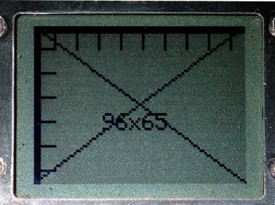
| Columns | 96 |
| Rows | 65 |
| Char matrix | - |
| Driver IC | Philips PCF88141) |
| Backlight | - |
| Arduino driver | |
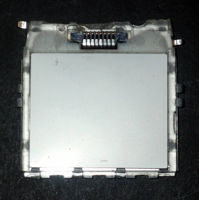
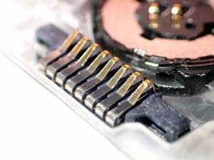
| Connector | pins |
| Num Pins | 8 |
| Pin spacing | 0.044” |
| Module size | mm |
| Connector pin-out | Arduino test rig | |||
|---|---|---|---|---|
| Pin# | Label | Description | Pin | colour |
| 1 | RST | Reset | ||
| 2 | CS | Chip select | ||
| 3 | GND | Ground | ||
| 4 | SDA | Serial data | ||
| 5 | CLK | Serial clock | ||
| 6 | VIO | IO power supply2) | ||
| 7 | Vdd | LCD power supply | ||
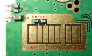
| 8 | VLCD | Internal voltage multiplier3) | ||
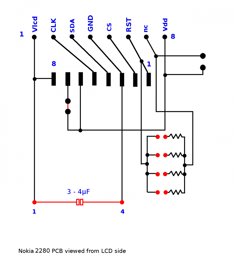
- Nokia 2280 LCD schematic:
Examples :
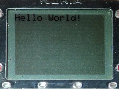
- Library: Adafruit_GFX_Library
- Library: PCF8814-Nokia-1100-LCD-library
- test.ino|
- Library: PCF8814_FB-library
- Bouncing_cube.ino
- PCF8814_libfb_Demo.ino
- PCF8814_libfb_HariChord.ino
Mounting on PCB
To reuse these in Arduino projects it is useful to have them mounted on a PCB.
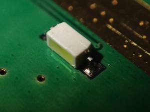
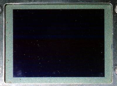
After disassembly the LCD's transparent light guide can be trimmed down to the size of the LCD:
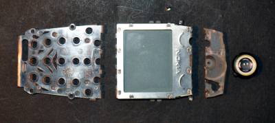
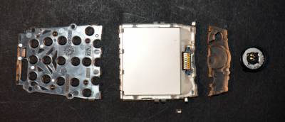
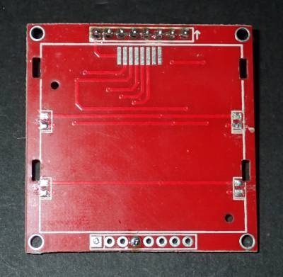
I have some spare Diymore Nokia 3310 adapter PCBs that can be modified to accommodate them:
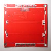
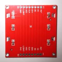
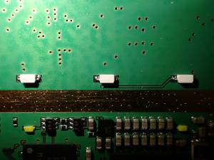
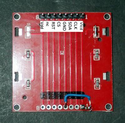
The four LEDs were removed from the top of the Nokia 3310 adapter PCB, and the capacitor on the bottom was replaced with a wire. The capacitor was relocated to the Vlcd pin where it again acts as an external capacitor for the LCD voltage booster. At this stage I have made no provision for a backlight.
| PCB Connector pin-out | Arduino test rig | |||
|---|---|---|---|---|
| Pin# | Label | Description | Pin | colour |
| 1 | Vlcd | Charge pump4) | - | - |
| 2 | Clk | Serial Clock | 13 | Green |
| 3 | SDA | Serial Data In | 11 | Blue |
| 4 | GND | Power Ground | Brown | |
| 5 | CS | Chip Select | 10 | Yellow |
| 6 | RST | Reset | 8 | Grey |
| 7 | nc | (no connection) | - | - |
| 8 | Vdd | 2.7V to 3.3V | Orange | |
Page Tools
electronic/lcd/nokia2280.txt · Last modified: 2022/10/07 09:21 by tony
 Except where otherwise noted, content on this wiki is licensed under the following license: CC Attribution-Share Alike 3.0 Unported