User Tools
Site Tools
LCD module data
Numeric
Character
Mixed
- ≡ Uniden FP203 ✘
- ≡ Uniden FP204 ✘
- ≡ VIP89Z G-Code ✘
Graphic
key: ≡ parallel, ↔ serial, ~ LVDS, _ unknown, ✘ discarded as not useful
| LCD Description | |
|---|---|
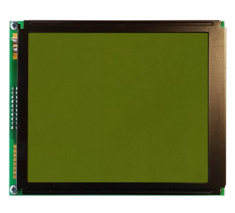
| Model | LMCCAT299C |
| Manufacturer | NAN YA Plastics Corp (Taiwan) |
| Recovered from | Wayfarer TGX 13722 1) |
| Board IDs | M299- Rev.A, D36072B1J, M299-GA, 36171103M336, LMCCAT299C |
| LCD type | positive |
| Polarizer type | transflective |
| Columns | 160 pixels |
| Rows | 128 pixels |
| Char matrix | 6×8 |
| Driver IC | T6963C |
| Backlight | yellow-green |
| Arduino driver | U8g2lib.h |
| Connector | pin header |
| Num Pins | 20 |
| Pin spacing | 0.1” |
| Module size | mm |
| Connector pin-out 2) | ||||
|---|---|---|---|---|
| Pin# | Ribbon cable#3) | IC pin | Label | Description |
| 1 | 2 | FG | Frame Ground | |
| 2 | 1 | 63 | VSS | Ground |
| 3 | 4 | 61 | VDD | Supply Voltage for Logic |
| 4 | 3 | VO | (variable) Supply Voltage for LCD | |
| 5 | 6 | VEE | Negative Voltage Output | |
| 6 | 5 | 18 | /WR | Data Write |
| 7 | 8 | 19 | /RD | Data Read |
| 8 | 7 | 20 | /CE | Chip Enable |
| 9 | 10 | 21 | C/D | Command Write |
| 10 | 9 | 1 | /HALT | Clock Operating Stop Signal |
| 11 | 12 | 2 | /RESET | Reset Signal |
| 12 | 11 | 10 | DB0 | Data Bus Line 0 |
| 13 | 14 | 11 | DB1 | Data Bus Line 1 |
| 14 | 13 | 12 | DB2 | Data Bus Line 2 |
| 15 | 16 | 13 | DB3 | Data Bus Line 3 |
| 16 | 15 | 14 | DB4 | Data Bus Line 4 |
| 17 | 18 | 15 | DB5 | Data Bus Line 5 |
| 18 | 17 | 16 | DB6 | Data Bus Line 6 |
| 19 | 20 | 17 | DB7 | Data Bus Line 7 |
| 20 | 19 | NC | No Connection | |
From a photo of the T6963C pins 3,6,7,9 are tied together, it is not apparent whether they go to Vdd or Vss. If it is Vss then maximum vertical resolution would be 64 v-dots, which seems a bit small for a 95mm high display, so I'll assume they're all tied to Vdd (confirmed by Markus).
| Display size selectors (hard wired) | ||
|---|---|---|
| Pin# | IC pin | Value |
| Dual | 54 | 1 |
| MDS | 3 | 1 |
| MD0 | 4 | 0 |
| MD1 | 5 | 0 |
⇒ 80 to 128 vertical dots, from the physical size most likely 128 (16 lines of characters).
128 is now confirmed.
| Display size selectors (hard wired) | ||
|---|---|---|
| Pin# | IC pin | Value |
| MD2 | 6 | 1 |
| MD3 | 7 | 1 |
=32 character columns (or this would give 80 columns if they're tied low, a bit excessive for this width display and not enough control chips to handle it).
32 is now confirmed.
| Display font size selectors | ||
|---|---|---|
| Pin# | IC pin | Value |
| FS0 | 8 | 0 |
| FS1 | 9 | 1 |
not sure what FS0 connects to, if Vdd then 5×8 font ⇒ 160 horizontal dots, if Vss then 6×8 font ⇒192 horizontal dots (but again not enough control chips to handle it).
Markus confirms FS0 is connect to Vss, 6×8 font ⇒ 192 dots wide. But there are not enough driver chips to handle more than 160 columns, so the above analysis is wrong. From the t6963 datasheet the scanning frequency is independent of font width.
So I must conclude that we have only 160 dots across to play with as the driver chips can't handle more.
A photo of a similar display in a Wayfarer TGX150 shows a text display of 27 columns by 16 rows of 7×8 characters. Actually 26 columns plus 4 pixels wide, so we have a 160 x 128 pixel display.
It turns out, that with the T6963C controller, the graphics pixel addressing mirrors the text rendering display buffer addressing. A side effect is that in graphics mode it is also only displaying the same number of bits per byte as for displaying text. So if the display is set to 6 bit (pixel) wide characters, it also only displays 6 bits of every byte in graphics mode. Anyway the U8G2Lib expects T6963C based displays to have 8×8 font set, so short of re-writing the appropriate U8G2 Library, we need to switch this to 8×8 fonts by tying FS1 to ground. Markus informs me that we need to lift this pin, rather than just cutting tracks, and then connect it to Vss (to Pin 8, FS0).
Additional info
- Chips on board: T6963C, T6A39A (x2) T6A40 (100pin) (x2) , 74HC40103D, 74HC74D, BA10324AF, MT62C256F-70LL
- Similar to OCM160128-1
- Similar to Di-Star DS-G160128STBWW
- Explanation of difference in U8GLib and U8G2Lib parameters https://github.com/olikraus/u8g2/issues/169 for T6963 displays
Examples :
Page Tools
 Except where otherwise noted, content on this wiki is licensed under the following license: CC Attribution-Share Alike 3.0 Unported

