Published 18 Feb 2020
Turbo Explorer
Overview
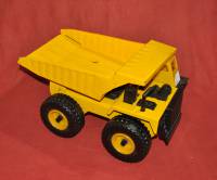
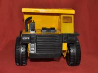
I needed a platform to try out the Dagu Explorer robot control board. So I built one using a plastic plate from an old CD ROM drive, a couple of geared motors, wheels from a “Turbo Diesel” dump truck toy (a knock-off of the Tonka Dump Truck?), and an Arduino Uno. I always try to avoid buying any parts, so recycle whatever is available.
Hardware description
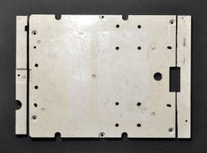
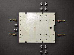
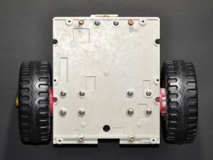
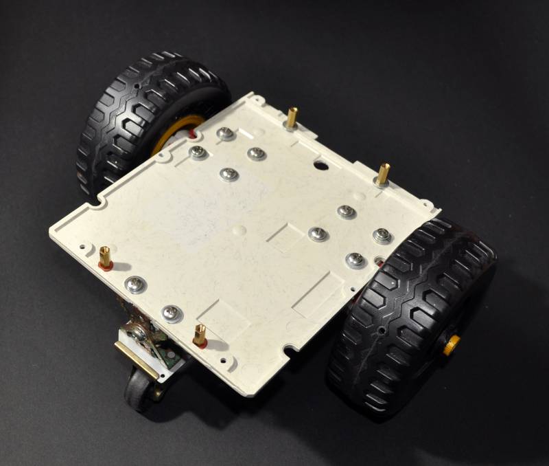
I made a platform from the plastic base plate of a Toshiba XM-3301B CD Rom drive, cutting it to about the same length as the Explorer board, so that the corner infra-red sensors would over-hang the ends. This was a mistake! It turns out that the sensors are easily bent in collisions, and it would have been better to have them slightly behind the corner edges of the base plate. (I subsequently remade the base plate from another CDRom, and used the first one as a template, so now the sensor have some protection).
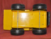
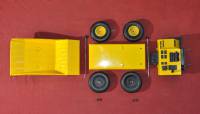
Originally I was going to use a broken toy dump truck as the platform, but the Explorer board did not really fit (and the corner sensors would not have been of any use). So I ended up just using two of its wheels.
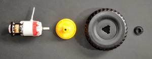
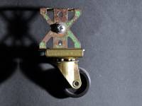
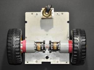
The two, 50 year old, 6V geared motors (Marx "mini Richard") were bolted to the plate and a single old furniture castor wheel was mounted using old Meccano L brackets on the front. As they are mounted 180° relative to each other, one motor has to run in reverse, this will probably accentuate any differences between them, the software will have to compensate for their different rotational speeds. The geared motors were bought to use in building a toy long before microprocessors or microcontrollers were ever invented, but never used. They have an adjustable gearbox that allows selecting gear ratios from 3:1 to 60:1. The wheels were mounted on the axles with their outsides facing in. As the hubs were recessed this allows the gearbox on the end of the motor to fit inside. This results in the wheels being mounted on the axles closer to the platform (the gearboxes extend beyond the edge of the platform).
The castor wheel has a ball-bearing axle, so rotates freely and is capable of operating with a far greater load than this robot will ever impose on it. The positioning of the components was dictated by the hardware - the motors were mounted facing opposite directions, not quite touching, which left their gearboxes and axles protruding beyond the edge of the platform. The wheels needed to be far enough forward so that they did not impede the corner sensors. The front castor wheel was mounted in the centre, as far forward as possible. Meccano L brackets that resulted in the platform being level were chosen to mount the castor wheel. The positioning of the standoffs to mount the Explorer board was dictated by the mounting holes of that board (a template was used). Washers were used so as to not stress the plastic parts too much, fibre washers were used in a couple of places as it is easy to trim a tangential flat along an edge of them to get them to fit against pre-moulded protrusions on the platform (could have just filed down the edge of a metal washer instead).
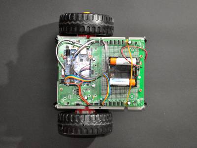
Assembled robot
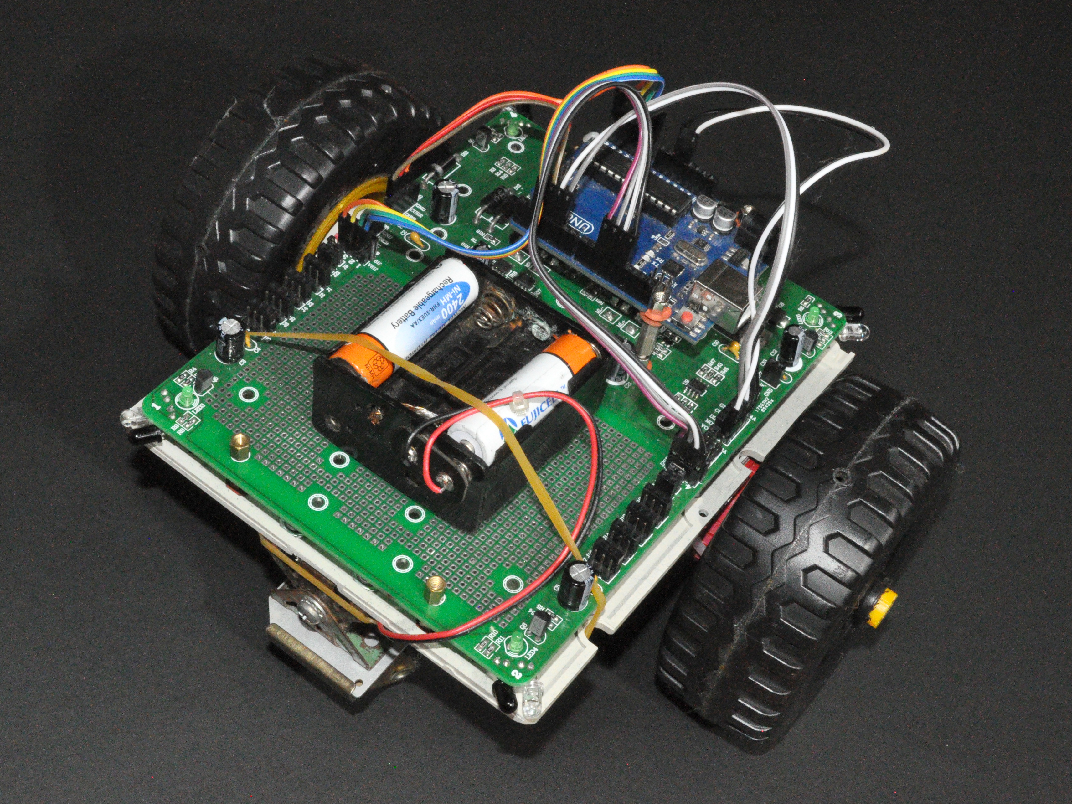
I then mounted the Explorer board together with an Arduino Uno and battery pack.
The Arduino Uno does not have a huge number of I/O pins, so can not connect to all the possible features supported by the Explorer board. But my motors do not have rotary encoders, and I do not have a working servo for the “Compound Eye” sensor anyway. What I did connect was the Direction and PWM lines for each motor (two digital and two PWM lines), the current sensor lines for each motor (two analog input lines), and the four corner infra-red collision sensors (four digital output and four analog input lines). This leaves two digital and two PWM outputs free.
The wheels are high enough that the battery pack could be mounted underneath, but for the time being it just rides on the top.
For the motors, the Explorer board uses 2 pin Molex connectors the same as found in many PC power supplies (internal plug connecting the mains wires, c0mes with high current wires attached). I modified an 8 AA cell battery pack to accommodate just 6 AA cells to provide a 7.2 to 8.4V battery for the system, found a plug (ex PC speaker I think) that matched the Explorer power jack. Strangely the Explorer board has large-pinned sockets for the outgoing power to the motors, but only a tiny battery socket through which all that power has to come!
Software
The Dagu example software was useful in understanding how to drive the edge sensors.
Conclusion
Experimentation with this robot platform was cut short by one of the motors stripping a gear, perhaps the motors were more worn out than I remember, or the plastic/nylon gears had simply dried out and become brittle with age. Unfortunately I haven't got an alternative low geared motors to replace it with.
References and Additional Resources
- Explorer robot control board.
If any referenced page no longer exists, try looking for its URL on http://archive.org.
