Published 16 Jan 2020
Explorer
Overview
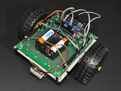
I recently came across parts of a robot system that turned out to be parts of a “Rover 5 Explorer kit”1) type robot platform. Rover 5 is a tracked chassis on which can be mounted a variety of robot controllers. Explorer is an interface board to facilitate connection of an Arduino or similar controller to the robot platform. An IR compound eye mounted on a pan/tilt assembly can be used to track moving objects or as a simple range finder.
The mainboard circuitry is similar to that found on the Dagu “Mr. General” and “Mr. Tidy” robots, and the software for the IR compound eye will work the same.
The robot was made by Dagu2)
Hardware description
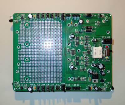
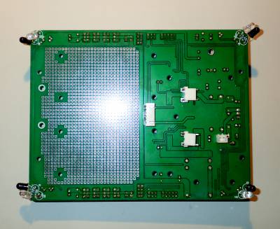
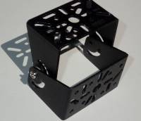
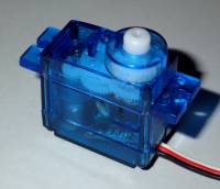
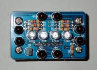
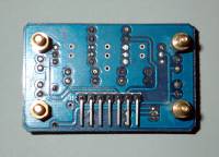
The hardware I have consists of a mainboard 3), 2 servo motors 4), and a tilt/swivel bracket 5) with an infrared “compound eye” 6), 7). The mainboard has a prototyping area, corner mounted infrared transmitter/receiver sensors, power regulators, h-bridge motor driver, motor current level sensor, motor rotary encoder interface, status LEDs, many servo/sensor plug/sockets, NiMH battery charging circuit, and mounting holes to suit Arduino boards, breadboards and servos.
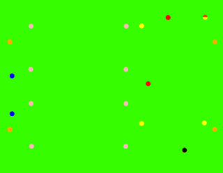
I found it useful to have a template that I could print out at 100% (I printed it as 171mm long by 132mm wide, but the printer might not be precise, so compare it with the board and reprint scaled up if necessary) and use for marking mount hole positions on my platform. The holes are colour coded as follows:
| Colour | Purpose |
|---|---|
| Orange | Mainboard mounting |
| Blue | Pan/tilt servo mounting |
| Pink | Breadboard mounting |
| Yellow | Arduino Mega mounting |
| Red | Arduino Uno etc mounting |
| Black | Heat sink mounting |
The tilt/swivel bracket, servos and compound eye form the “head” of the robot, and with suitable software allow the robot to track objects close to it (< 200mm).
My version of the mainboard8) can be seen in some photos of the Rover 5, eg https://sites.google.com/site/daguproducts/home/download-page/IMG_2297 (small).jpg, but most photos show a presumably later version with a row of 6 screw terminals at the rear left side of the board.
The corner infrared sensors are vulnerable to being displaced by collisions, and end up effectively inoperative. So some consideration needs to be made to protect them, eg mounting them so they do not protrude beyond the edge of the chassis, or adding a bumper/guard. Also there is a small amount of light that comes out the side of the LEDs, and that can muck up distance sensing, especially if the LED and phototransistor are touching. The LEDs are rated as 100mA maximum continuous current, as wired the circuit doesn't get anywhere near this, a 47Ω series resistor would still limit current to safe levels (nominally (5.0-1.4-0.2)/47=72mA, maximum (5.2-1.2-.2))/44=86mA),
The infra-red corner sensors can either be read as digital or analog inputs. The Mr Tidy example code treats them as digital inputs - effectively making them fixed distance, very short-range sensors. The Explorer example code treats them as analog inputs - so although still short-range you can set a distance threshold. Both robot platforms that I've built with this board have had the wheels or tracks extending well beyond the explorer board, which cuts down their effectiveness as they really are only short range sensors, so I will have to build something with a smaller footprint.
Navigating and avoiding obstacles with the corner sensors has severe limitations:
- Short range, <200mm
- Background lighting can over whelm them (eg sunlight when outside)
- They really only detect obstacles at their height, so low walls and overhangs are not detected
- Narrow obstacles aren't detected
- The colour of walls greatly affects how far away they are detected (eg dark not detected as easily as white)
- The sensors are at 45º, so for example you can't easily tell whether an object is in front or to the side
In my example of this board, the repeatability of distance readings is quite good - with a spread of 4 values (ie +/- 2 about the mean) for stationary readings (both robot and environment not moving) for 3 out of the 4 sensors. The 4th sensor seems to vary more than twice as much, maybe one of the components (resistor, photo diode, photo transistor) is faulty.
Software
Despite the board having full H-bridge driver hardware, the example Explorer code (file dated 24/01/2011) assumes that the main drive motors are of the analog pulse-width driven, continuous rotation, servo type. That is they only require a single control line for forward, back and stop control. The example software for the “Mr Tidy” robot handles normal PWM DC motors, and has the same corner infrared collision detection hardware, but it also has a lot of other features and so requires a controller with a lot more I/O pins than an Arduino UNO.
Examples
Used to control a 3 wheeled robot testbed Turbo Explorer.
References and Additional Resources
Rover 5
Mr. General, related platform with similar hardware
-
- http://www.arobose.com/docs/Mr.General_Instruction_manual.pdf Mr. General instruction manual
Mr. Tidy, related platform with similar hardware
- (Has the same corner sensors and PWM main motors)
