User Tools
Site Tools
Published 13 Apr 2001
Converting the Compaq PS-7331-1C power supply for use on an ATX Motherboard
Disclaimer
Make these modifications at your own risk to your personal health and safety and that of your computer!!! Such modifications will no doubt void any warranties on any equipment connected to it. Normally the power supply outputs are of low voltage and safe. If you don't open the power supply case you shouldn't be exposed to any dangerous voltages BUT it is entirely conceivable that by mis-wiring the outputs you may induce a fault condition that could cause a fire or produce high voltage on the outputs. I can accept no responsibility for any damages or actions resulting from implementing these changes. This description is distributed for informational purposes only, and not to encourage you to make any such modifications.
(Your mileage may vary ![]() )
)
Personally I believe the described re-wiring to be safe, and the power supply will normally shut down on fault conditions.
The Compaq PS-7331-1C power supply has three motherboard connectors. One is an exact ATX type connector (P2), but is wired completely differently! There is also a similar smaller connector labelled P3, and a black one with all the control signals etc labelled P1.1)
What needs doing:
To rewire P2 to the ATX standard you have to extract all the wires (with their pins) from the socket and insert them into the appropriate positions in the socket. Additionally you have to cut off three of the wires to P1 (thin orange, grey and red) solder them onto the right type of pins for P2 and insert them in the right positions too. That's all, it took me 2 hours, but that included working out what needed to be done.
Detailed how to do it:
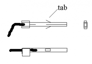
If you examine the 20 sockets of P2 you can just make out through the transparent plastic that each pin is held in by little tabs that stick out half way along each pin. One on either side of each pin. To extract the wires with their pins without damaging the pins so they can be re-used reliably, I use a very small diameter jewellers screw driver (thin but tough). This can be slid down each side of each pin (from the non wire end), and a little twist causes the flat blade of the screw driver to press the tabs against the pin. The pin can then be pulled out by it's wire. If it doesn't come easily, operate on it again. You must depress these tabs otherwise they will be bent back and almost certainly break off, leaving nothing to hold the pins when re-inserted.
Perhaps practice on P3 as it isn't needed for anything (not on my motherboard anyway!). (If you do ruin any pins from P2, the same colour wires from P3 can be used instead.
Next carefully bend the tabs back out from the pins (the point of a craft knife is useful for this). The tabs should stick out on a slight angle, approx. 30 degrees.
Then insert appropriate coloured wires in the appropriate sockets (see table below).
There should be three spare unused wires (two red, one black).
Finally cut the pins off the three spare wires and cut the orange, grey, and red wires from P1. Bare the ends of the wires and solder each to a pin, taking care not to damage the pins, and ensuring the join is small enough to allow the pin to be fully inserted back into the socket.
Insert the re-made pins into the appropriate sockets (as per 'thin' wires listed in table below)
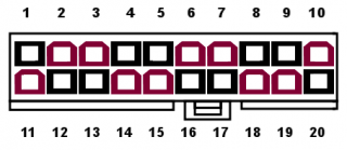
The diagram below is of the ATX style connector, viewed looking down on the wire side of the connector.
The table below lists the original wires, and the correct wires to match the ATX standard. All of the original wires of the same colour have the same function, so it doesn't matter which goes where (so long as they are the right colour!). The three wires that come from P1 can be readily identified because they are thinner than those from P2.
| Original wire | ATX wire | Pin | Name | Description |
|---|---|---|---|---|
| Red | Brown | 1 | +3.3V | Power +3.3V |
| Black | Brown | 2 | +3.3V | Power +3.3V |
| Black | Black | 3 | GND | Ground |
| Black | Red | 4 | +5V | Vcc +5V |
| Black | Black | 5 | GND | Ground |
| Black | Red | 6 | +5V | Vcc +5V |
| Black | Black | 7 | GND | Ground |
| Black | Orange (thin) | 8 | PWROK | Power Good |
| Black | Red (thin) | 9 | 5VSB | +5V Standby |
| Brown | Orange | 10 | +12V | Power +12V |
| Red | Brown | 11 | +3.3V | Power +3.3V |
| Orange | Blue | 12 | -12V | Power -12V |
| White | Black | 13 | GND | Ground |
| Blue | Grey (thin) | 14 | PS-ON | Remote Power ON/OFF |
| Red | Black | 15 | GND | Ground |
| Red | Black | 16 | GND | Ground |
| Red | Black | 17 | GND | Ground |
| Red | White | 18 | -5V | Power -5V |
| Brown | Red | 19 | +5V | Vcc +5V |
| Brown | Red | 20 | +5V | Vcc +5V |
Important: Clean up any left over wires (insulate the ends and tie them back) so they can't short out.
Then the most important step, Test it!
Use a multimeter to test the outputs (relative to the ground wire from one of the disk drive connectors). With the power plugged in Pin 9 (standby +5v) should show 5V +/- 5%. Pin 14 (power on/off) should also show something (1.5 to 5V). All other pins on the ATX connector should be 0V.
Before switching on you will probably have to have a dummy load attached to the power supply to stop it shutting down immediately when it detects no load. I use an old, large 8MB Full Height 5.25” Hard disk attached to one of the hard drive power connectors. Use something that takes a good bit of power on both 5V and 12v lines, and is either faulty or you don't mind destroying if something goes wrong !
The power supply can be switched on by shorting pin14 to ground (a wire or bent paperclip from pin 14 to pin 13 should do). Fan should start up, and all voltages should be as listed above (+/- 5%).
'Power Good' should come up to 5V moments after the rest, but you may not be able to detect the delay.
Page Tools
 Except where otherwise noted, content on this wiki is licensed under the following license: CC Attribution-Share Alike 3.0 Unported
