User Tools
Site Tools
Published 6 Aug 2021
Ltl Acorn 5210a
Overview
| Camera data | |
|---|---|
| Model | Ltl-5210a |
| Manufacturer | Zhuhai Ltl Acorn Electronic Co.,Ltd |
| Board IDs | |
| Type | TrailCam |
| Memory card | SD |
| Date | 2014 |
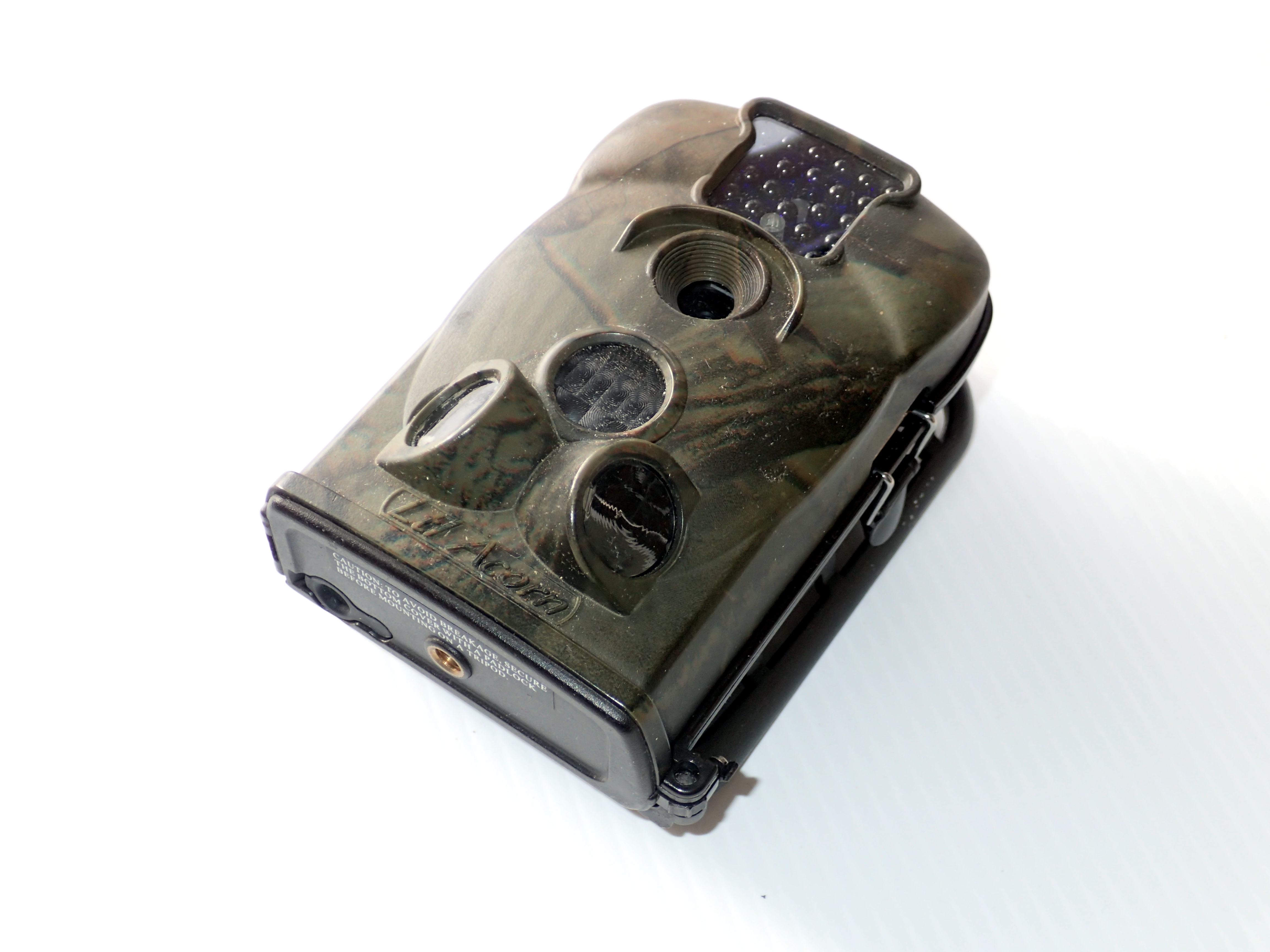
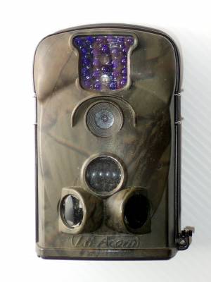
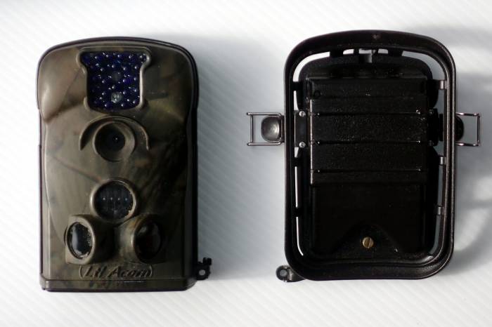
The Ltl Acorn 5210a (ltl-5210a), is a Trail-cam/Scouting camera/Game camera/Surveillance camera with night vision capability.
Designed for monitoring wildlife or for security/surveillance it is reasonably weatherproof, and can run for up to 6 months without changing batteries. The case is coloured either camouflage green or black.
Hardware description
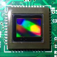
The Ltl Acorn 5210a has a 5 Megapixel camera (interpolated to 12Mp 2)), and two passive infrared sensors. One sensor (the “prep” sensor) is lit by two lenses angled at 50º to either side.
Described as a 12MP camera in advertising, yet it is also described as only having a 5MP sensor. The extra inserted pixels in the 4000 x 3000 images are interpolated (ie average of adjacent pixels) - ie literally a waste of space on your SD card just for marketing hype and actually a degradation of picture quality.
| Feature | Specifications |
|---|---|
| Lens | F = 3.1; FOV = 52°; Auto infrared cutout |
| Image sensor | 5 Megapixel (2560 x 1920) colour CMOS |
| ISO sensitivity | |
| Image size | 5 Mp (2560 x 1920), 3Mp (2048 x 1536), 12Mp (4000 x 3000) |
| Video size | 640 x 480 at 20 fps, 320 x 240 at 20 fps |
| Infrared flash range | 20 m |
| LCD screen | 48 x 35.69 mm; 480 x 234 pixel; 16.7 M colour |
| Memory SD card | Up to 16 GB, preferably HC 10 speed |
| PIR sensitivity | High/Normal/Low |
| PIR sensing distance | 20 m(below 25°C) |
| Prep PIR sensing angle | Left and right light beams form an angle of 100°; Each lens covers 10° |
| Main PIR sensing angle | 35° |
| Operation mode | Day/Night |
| Trigger delay | 1 sec (when using the 2 GB SD card) |
| reTrigger interval | 0 sec to 60 min |
| Still photos | 1 to 3 |
| Video length | 1 to 60 sec |
| Photo plus video option | Takes still photo then video |
| Sound plus video | no |
| Time lapse capture | 1 sec to 24 hours |
| Time lapse plus photo | no |
| Time stamp | ID, moon phase, temperature (ºF, ºC), date and time |
| Time stamp videos | Date and time |
| Password | 4-digit PIN |
| Device ID setting | 4 alphanumeric characters |
| Power supply | 4 x AA (8 x AA with backpack). Or external 6V DC |
| Stand by current | 400 µA |
| Stand by time | 3 months (6 months with backpack) |
| Power saving | Auto power off after 2 minutes of keypad inactivity |
| Power consumption | 150 mA (+500 mA when infrared LEDs fire) |
Components
- Hynix H5DU2562GTR-E3C 256Mb DDR SDRAM
- Hynix HY27US08561A TPCB 32Mx8bit NAND flash memory
- PIC16F690 -II/SS 8-bit PIC microcontroller
- Novatek NT96211FG 1205-BS A1585541
- XLltos LHi 778 Dual Elements Pyroelectric Infrared Detector
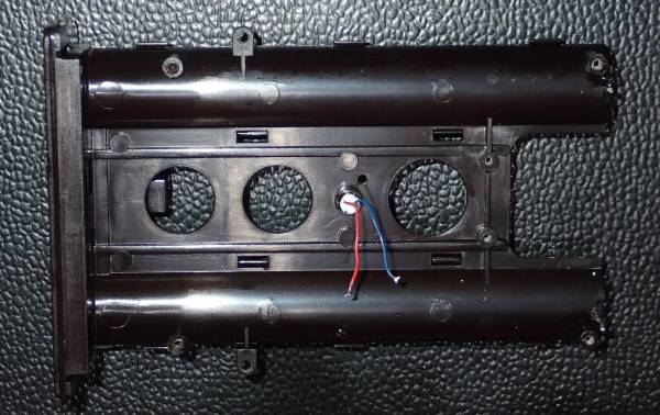
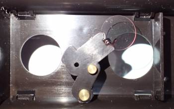
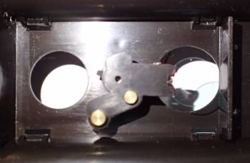
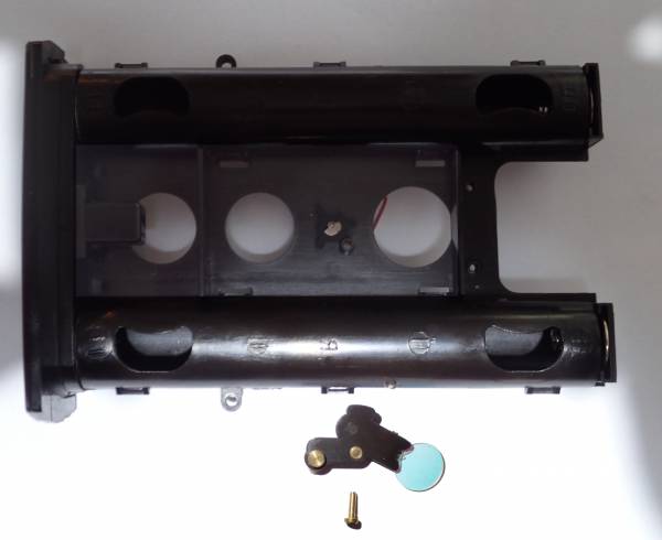
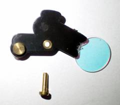
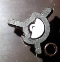
The Infrared filter is moved in front of the lens when the light levels are high enough to film without the infrared LEDs switched on. When the light levels drop, the filter is switched out, the infrared LEDs are switched on, and the image is rendered in black and white (so even if there is still some colour reaching the camera we only get a grey scale image). The filter actuator is actually just a very small motor which spins clockwise or anticlockwise depending on the power polarity. A rubber cam limits its rotation, and engages with the filter mechanism.
Back Pack
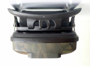
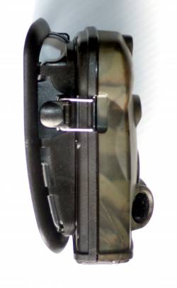
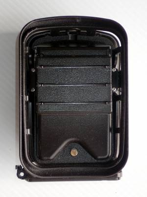
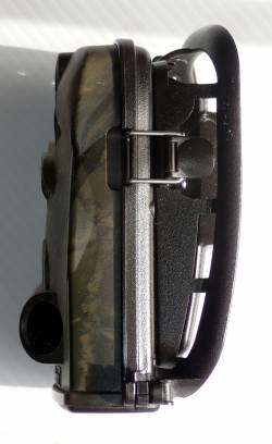
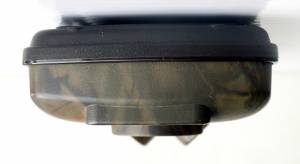
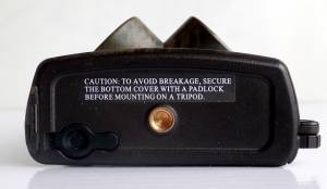
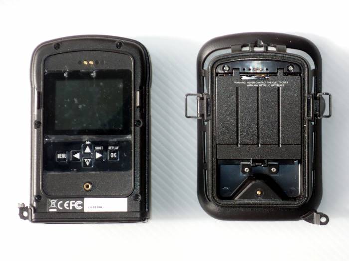
It comes with an optional(?) “back-pack” which clips on the back and has space for a battery of another four AA cells. This doubles how long the camera can go before changing batteries to about 6 months. The back-pack also aids mounting the camera on curved surfaces like tree trunks as it has a slightly flexible, curved back, which can be strapped to a tree trunk. The camera is attached to the back-pack via two clips and a hand tightened screw. The camera can be detached from the back-pack by opening the two clips, which makes it easy to unmount the camera and check the settings or review the photos in the field. If you want to prevent this then the screw can be tightened to secure it to the camera before the back-pack is fixed to the tree etc.
Operation
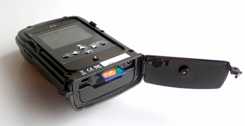
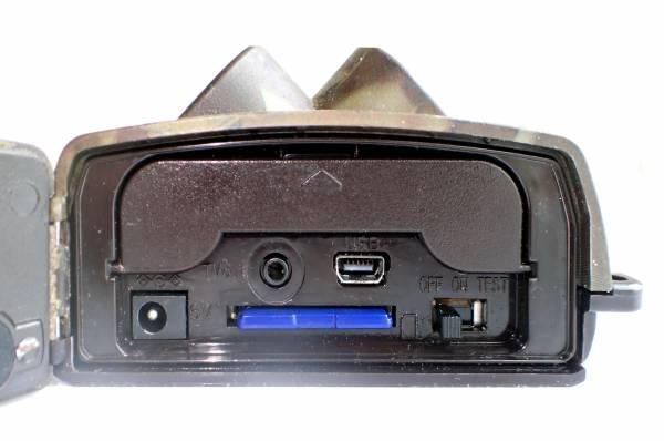
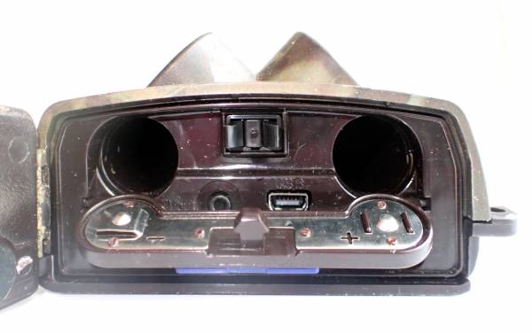
Opening the cover at the bottom reveals the battery compartment, external power socket, video out socket (NTSC), USB socket, SD card, and OFF/ON/TEST switch.
”Test” mode allows the changing of parameters, check of the sensor field of detection, and review of images stored.
For normal operation it is switched to the middle position :”'On”. It flashes red twelve times to confirm operation and to give you time to leave before the camera is armed and ready to take photographs.
The prep sensor wakes up the camera so that it is ready to trigger when movement is detected on the main sensor. This delay between the “prep” sensor being triggered, and the main sensor being ready is about 0.8 seconds. The idea being that the camera can stay in low power standby mode (400µA) for long periods and go to full power only when something to photograph is imminent.
It can be set to take a burst of photos or a video (or both) every time the PIR sensors detect motion.
In time-lapse mode it can take a burst of photos and/or a video at regular intervals, and it also takes PIR triggered images too if they occur (timing doesn't appear to be that precise, as when set for a 10 second interval, the delay between images varied from 8 to 9 seconds). You can set the PIR sensitivity to ”Off” if you don't want the additional movement triggered images.
There are also two start/stop timers so that the camera can be made to be only active during specified periods.
"Test" mode menu
Blue menu background, firmware V3.521A:
| Setup | |
|---|---|
| Mode | Camera/Video/Cam+Video |
| Format | |
| Photo Size | 5MP/12MP |
| Video Size | 640×480/320×240 |
| Set Clock | |
| Picture No. | 01 Photo/02 Photos/03 Photos |
| Video Length | AVI 1 Sec thru AVI 60 Sec |
| Interval | 0 Sec thru 60 Min |
| Sense Level | Off/Normal/High/Low |
| Time Stamp | On/Off |
| Timer1 | On/Off |
| Timer2 | On/Off |
| Password Set | On/Off |
| Serial NO | On/Off |
| Time Lapse | On/Off |
| Side PIR | On/Off |
| Default Set | |
Security
You can set a four digit PIN/password to prevent access to the settings menu and the photos in the camera. But this will at best show you when the camera has been tampered with, and will only prevent the most casual interference. The PIN doesn't encrypt the SD card, so it is easily readable on other devices, and easily wiped too. If you want to use the camera for security purposes you need to ensure it is well hidden, and above the eye-line of most people, or physically in-accessible as apart from the SD card being easily wiped or removed, the most likely scenario is that someone would steal the camera. There are lock-boxes available to hold the camera, and if this was secured well enough not to be stolen, the SD card would probably survive even if the camera was smashed in-situ.
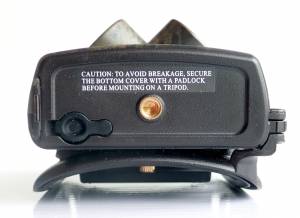
The lower door, which covers the battery holder, USB and other sockets, and SD card slot, can be secured with a small padlock. Again this will prevent casual interference, but obviously the plastic latch that would hold it could be broken off easily, if not accidentally.
Common faults
Many problems are evident if the batteries are too low a voltage, or insufficient capacity. So rechargeable batteries are marginal (too low a voltage, although plenty of capacity when charged), and the old zinc batteries don't seem to work well. Alkaline and lithium batteries work best. So if there are problems, try fresh batteries first.
The OFF/ON/TEST switch appears to suffer greatly after a long period of use, presumably water ingress and dirty contacts. This most often shows up as the camera not switching into ”Test” mode, but rather stays in normal operation mode. A squirt of WD-40, or similar, usually helps, although you probably need to take the cameras back off to be able to squirt effectively into the switch. Also note that the camera won't switch to ”Test” mode if there is no SD card detected. If there is no SD card present the Acorn logo and sound appears, then the screen goes blank with no live screen or menu.
The second most common problem that I see are horizontal lines across the screen, or a completely blank (or lit up white) screen. The lines are caused by iffy connections to the LCD, not the PCB flex cable that connects to the main board, but within the module itself. Pressure around the edges of the LCD may help, but I suspect there is no real cure. A completely white screen is possibly the result of the PCB flex cable not being seated properly, so carefully reinserting it may help.
Another fault is the infrared filter coming loose because the press fitted brass pin, that the filter pivots on, has come out. If the pin has been lost, a substitute can be made out of a small brass nail cut to length.
The hard plastic case can be a bit brittle, and the hinge to the cover at the base, the latch on that cover, the hinge on the battery door and the edges where the back-pack latches on, can all get broken easily. Breaking the thin pins that are the hinge on the battery cover isn't as bad as it seems, as the battery cover is actually held in place by its latch, and the “hinge” just keeps it from falling out when open/unlatched.
Examples
Tear down
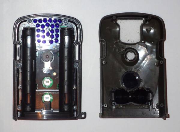
The back-plate is held on by six 7.5mm long screws, and reveals the sensors, camera, infrared filter and infrared LED board. These are all mounted on a printed circuit board attached to an inner plastic frame that also contain the battery holder. This frame is connected to the front-plate by two 4.5mm long screws.
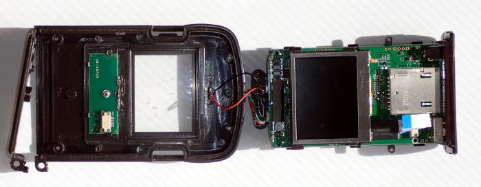
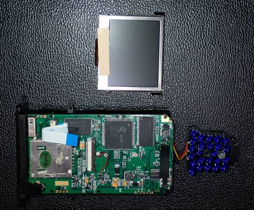
After removing the two screws and releasing the PCB flex cable to the keypad, it opens out to reveal the colour LCD and SD camera card socket:
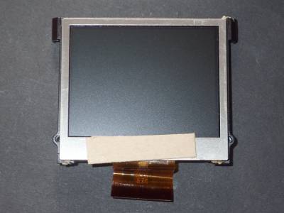
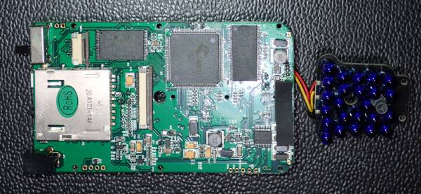
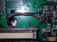
The LCD connects by another PCB flex cable to the mainboard, and the infrared LED assembly is mounted on the inner frame by two 4.5mm long screws, and attached via two wires to a socket on the main board:
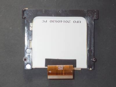
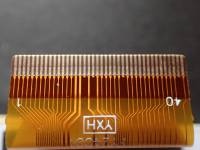
The rear panel LCD is connected via a 40 pin flex cable, and mounted in a plastic carrier.
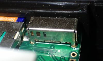
The OFF/ON/TEST switch (next to the SD socket in the picture above) is a weak point in these cameras. When the contacts get dirty or corrode it becomes unreliable, and results in a variety of symptoms. Most commonly it is evidenced by the camera being unable to be switched into ”Test” mode.
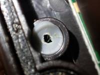
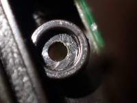
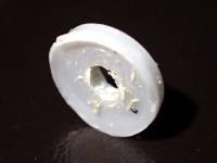
The screws, securing the backplate, screw into mounts through silicon washers to minimise moisture ingress :
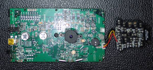
Main printed circuit board with PIR sensors, camera, and infrared LEDs:
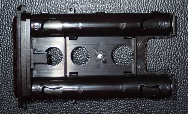
Inner frame with circuit removed, showing the infrared filter actuator in the centre:
Infrared filter and actuator:
References and Additional Resources
Page Tools
 Except where otherwise noted, content on this wiki is licensed under the following license: CC Attribution-Share Alike 3.0 Unported
