

Published 15 Oct 2026
Xc4454 LCD Keypad Shield

| Shield Description | |
|---|---|
| Model | XC4454 |
| Manufacturer | made in China |
| Brand | Duinotech |
| Clone of | DFRobot LCD Keypad Shield (2009) |
| Other designations | DFR0009 |
| Arduino compatibility | Uno |
| Type | LCD with keypad |
| Voltage | 5V |
| Software | |

| Arduino pin usage | ||
|---|---|---|
| Pin | Label | Shield function |
| A0 | A0 | Button inputs |
| D4 | DB4 | LCD D4 |
| D5 | DB5 | LCD D5 |
| D6 | DB6 | LCD D6 |
| D7 | DB7 | LCD D7 |
| D8 | RS | LCD Register select data/control |
| D9 | E | LCD enable |
| D10 | DB10 | LCD Back-light |
Overview
A standard alphanumeric LCD with 2 rows of 16 characters, which can be driven by the standard Arduino 4bit display drivers. The LCD has a blue backlight, that can be turned on and off (default on), but see notes below about a design flaw.
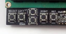
It also has a keypad of six push-buttons. One is to reset the display and attached Arduino, the other five are programmable inputs.
As it uses a parallel input LCD it needs to use a lot of Arduino pins (eight), although it has minimised this by only using one for the 5 push-button inputs.
Features
- 16 Columns x 2 rows of text display
- Blue backlight
- 6 Push button keypad (labeled “select”, “up”, “down”, “left”, “right” and reset)
- Contrast control
- Display uses standard 4bit LCD library

Design Flaws
Andy Gock mentions on his library page a flaw in the design of the backlight control : “when pin 10 is set to output, and set high, it could cause the IO pin of the MCU (the main Atmel chip) to deliver too much current (over the datasheet’s maximum rating)”. To avoid this:
  To turn the backlight on, set pin 10 as input.
  To turn the backlight off, set pin 10 as output, and immediately set output low (never high!)
From the published schematic I can see that the Arduino D10 drives the base of a transistor directly (with no current limit resistor), this may be the problem he describes.
| An illustration of two different suggestions to remedy this fault : |
|---|

On forum.arduino.cc bperrybap says “The best way to test for an issue is to actually measure the current on the D10 pin when it is being driven high. To do this, wire up the shield as described above but then measure the current between the D10 pin and VCC. Set your meter for current with + probe going to VCC and - probe going to the D10 pin on the shield. If you measure more than about 30ma, the backlight circuit has the issue.”
I can't confirm the exact wiring of my example of this shield, but I get a current of about 38mA through my meter if I use it to short pin D10 to VCC (D10 set to input mode for it's own safety). I presume this is all going through the base-emitter of the driver transistor, and is approximately what the Arduino would be sourcing from pin D10 if I set D10 HIGH. The absolute maximum output per pin on the original Uno is 40mA, so my example has the fault as described above.
Schematics

Examples


References and Additional Resources
 Except where otherwise noted, content on this wiki is licensed under the following license: CC Attribution-Share Alike 4.0 International