Published 29 Nov 2018
Arduino METP0000 Driver Library
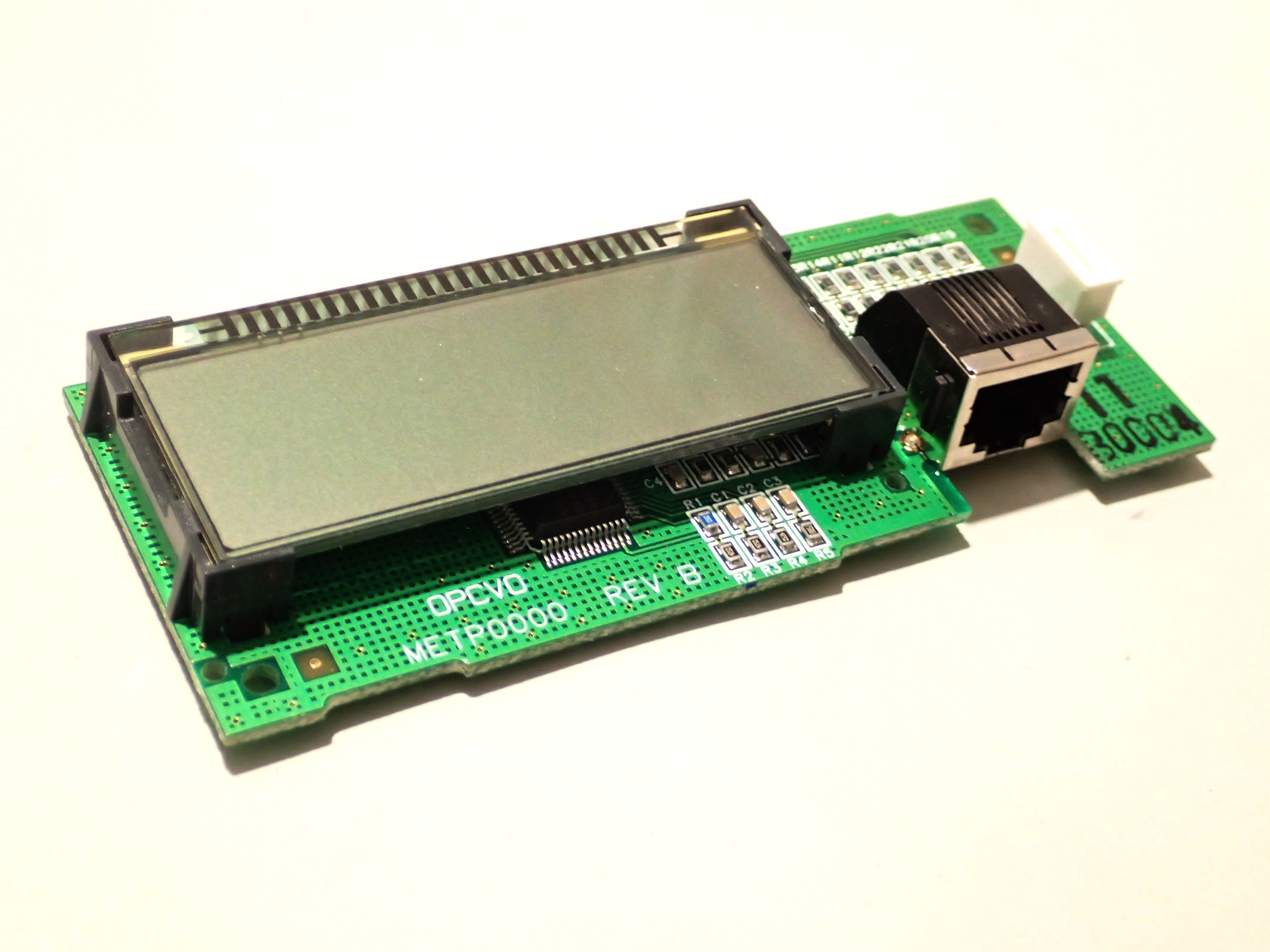
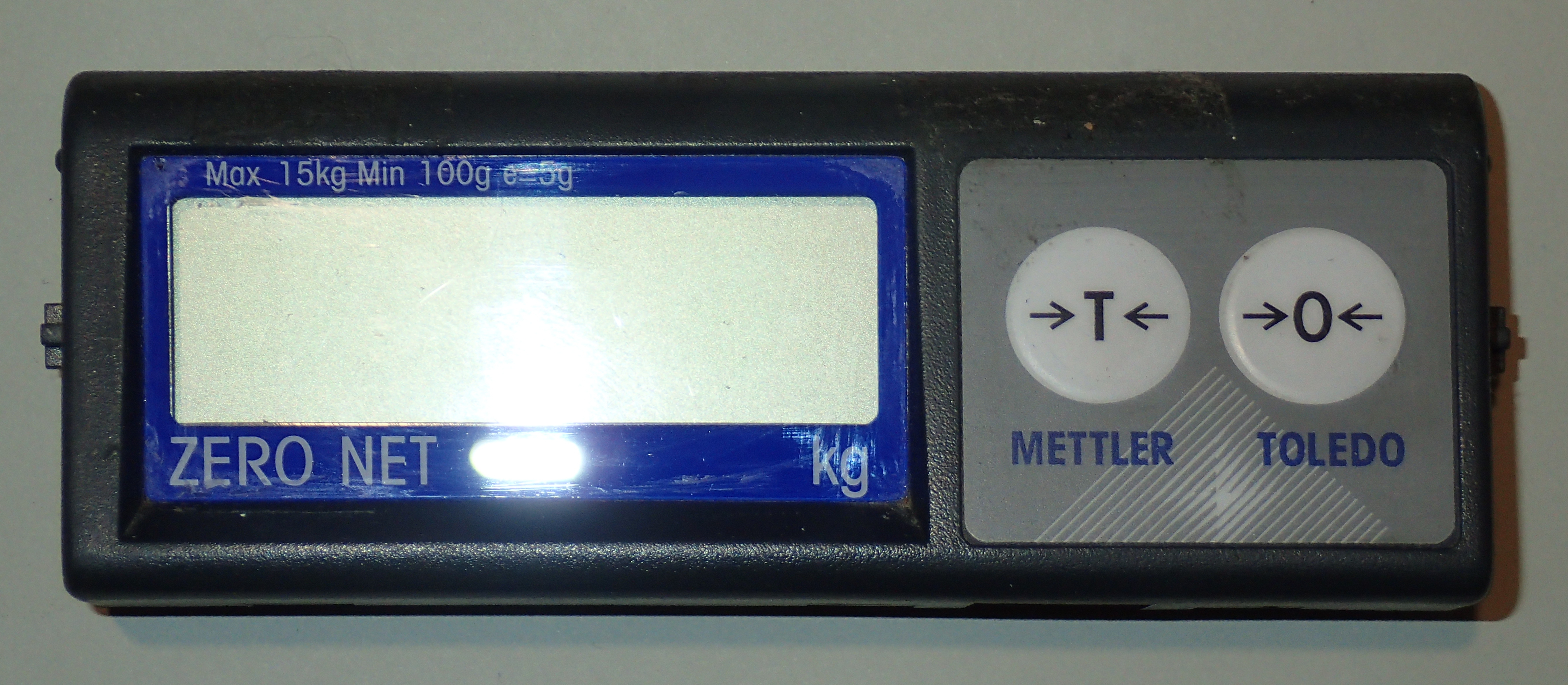
I have a display panel from a faulty Mettler Toledo Model 8217 weigh scale, that I wish to use in an Arduino project. This a 1 line by 6 digit, 7-segment, LCD status display, controlled by an NEC μPD7225 serial interfaced LCD controller/driver chip.
Overview
I looked for an Arduino library that would talk to this module, but failed to find one. But there were a few drivers for 12 digit μPD7225 modules 1), so I had somewhere to start.
I based the structure of my library module on a standard Arduino library for the Hitachi HD44780 chip, LiquidCrystal.cpp. The programs included here are helloworld5.ino, fourdigitdemo2.ino, metp0000_lib.h, metp0000_lib.cpp.
The NEC μPD7225 has a command set completely different from the Hitachi HD44780, it is used for 7-segment digits rather than 5×7 dot matrix characters, and it has a serial interface and reset pin.
Hardware description
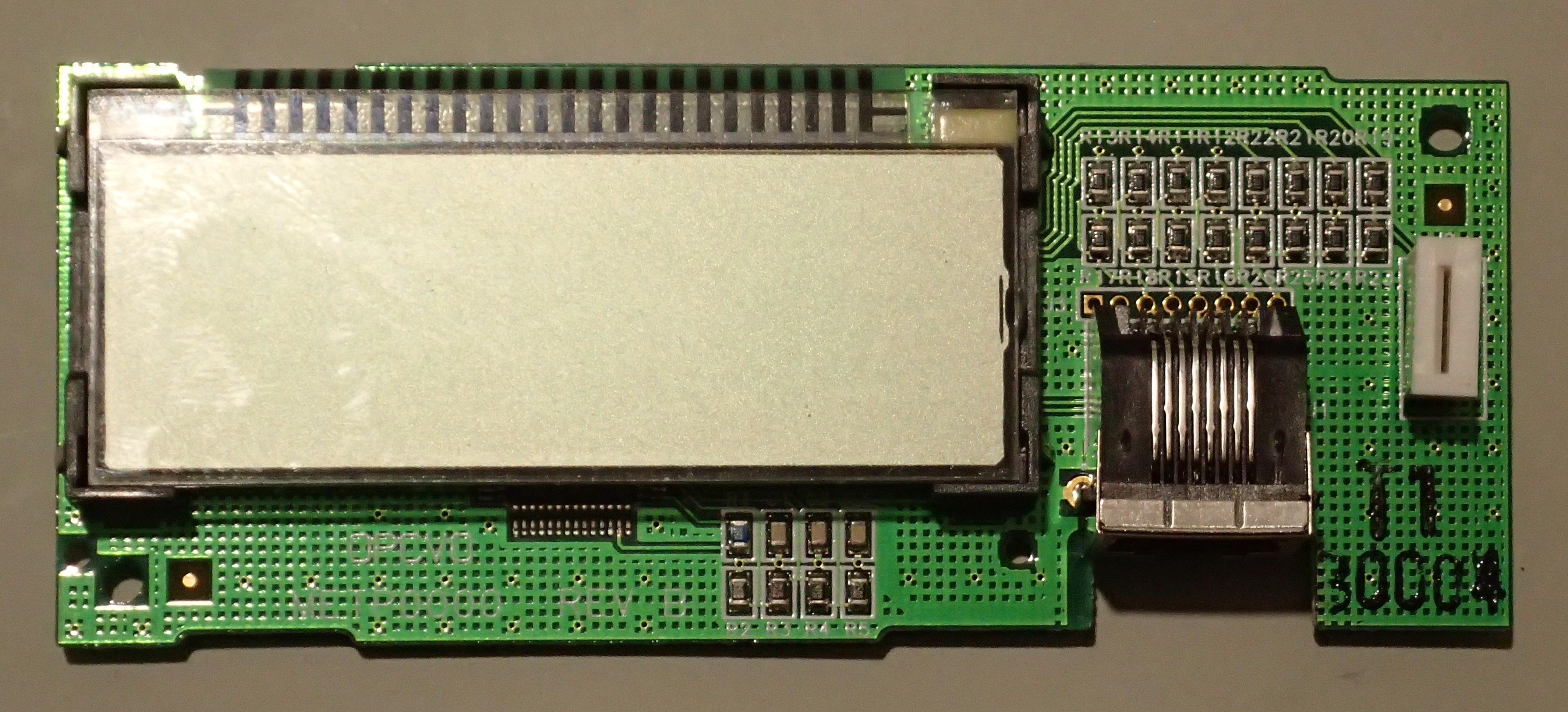
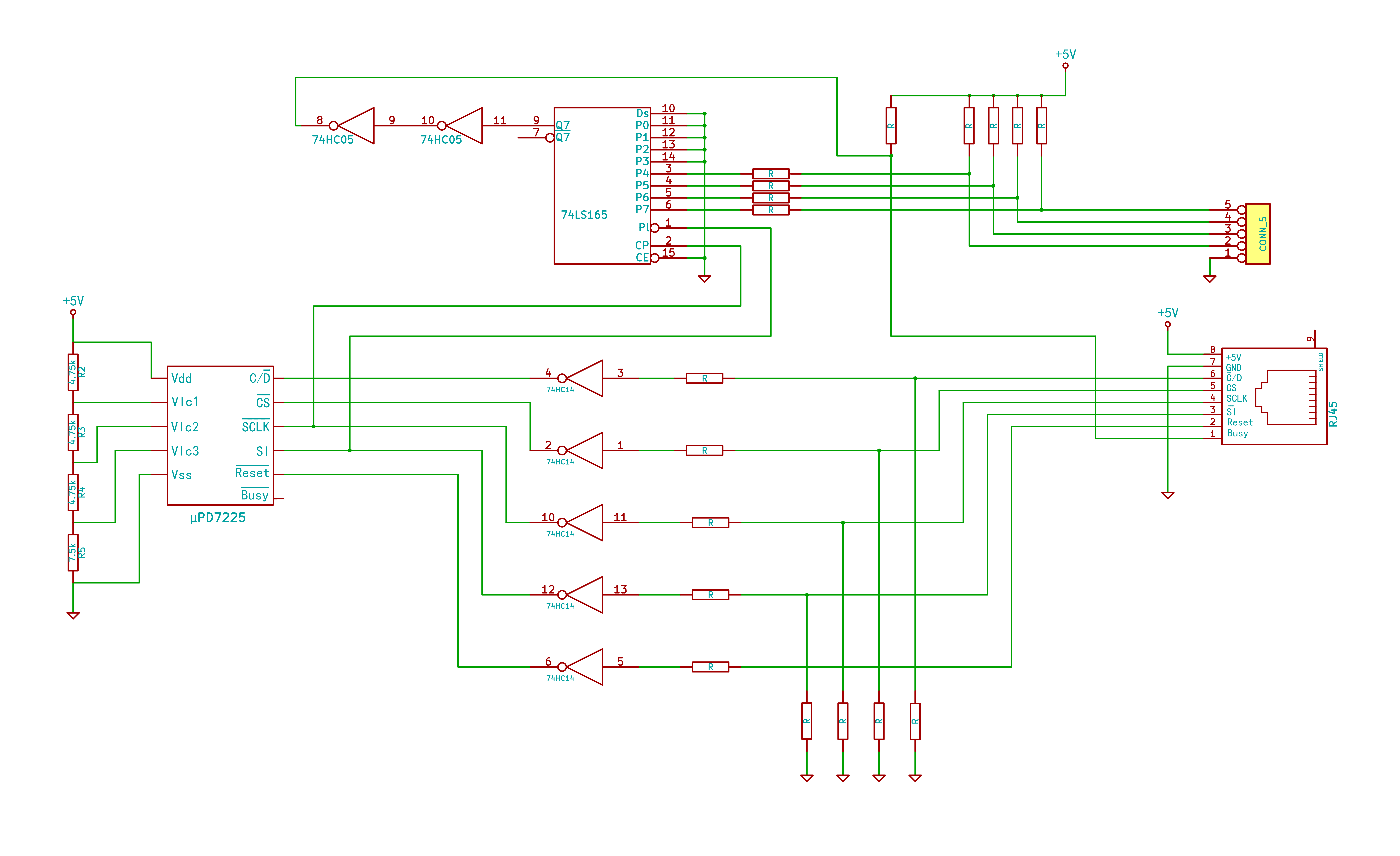
The controller consists of a single NEC D7225GB (μPD7225) chip, with a Schmitt trigger inverter input buffer (74HC14), another inverter (74HC05) and an 8-bit parallel-in/serial-out shift register (74HC165). The inverters mean that all the control signals to the μPD7225 are inverted, but this is easily accommodated in software. The control lines are brought out on an 8 pin RJ45 style connector (as used for twisted-pair Ethernet). The signals are are “Busy”, “Reset”, “SI” (serial input), “SCLK” (serial clock), “CS” (chip select) and “C/D” (control/data). Initially I interfaced all the control lines, but realised that I didn't need to use the Reset or the C/D line. Reset could be wired to do a reset at power on, and C/D could be tied low which would hold the chip in command receipt state continually. The other two pins are +5V and Ground.
The shift register appears to be used to encode the two front panel push-button switches, and then clock the serial data back out via the Busy line. I haven't investigated this, nor tried to use it. I think the μPD7225's Busy line goes through a buffer or two and is wire-ORed with the data from the push button switches.
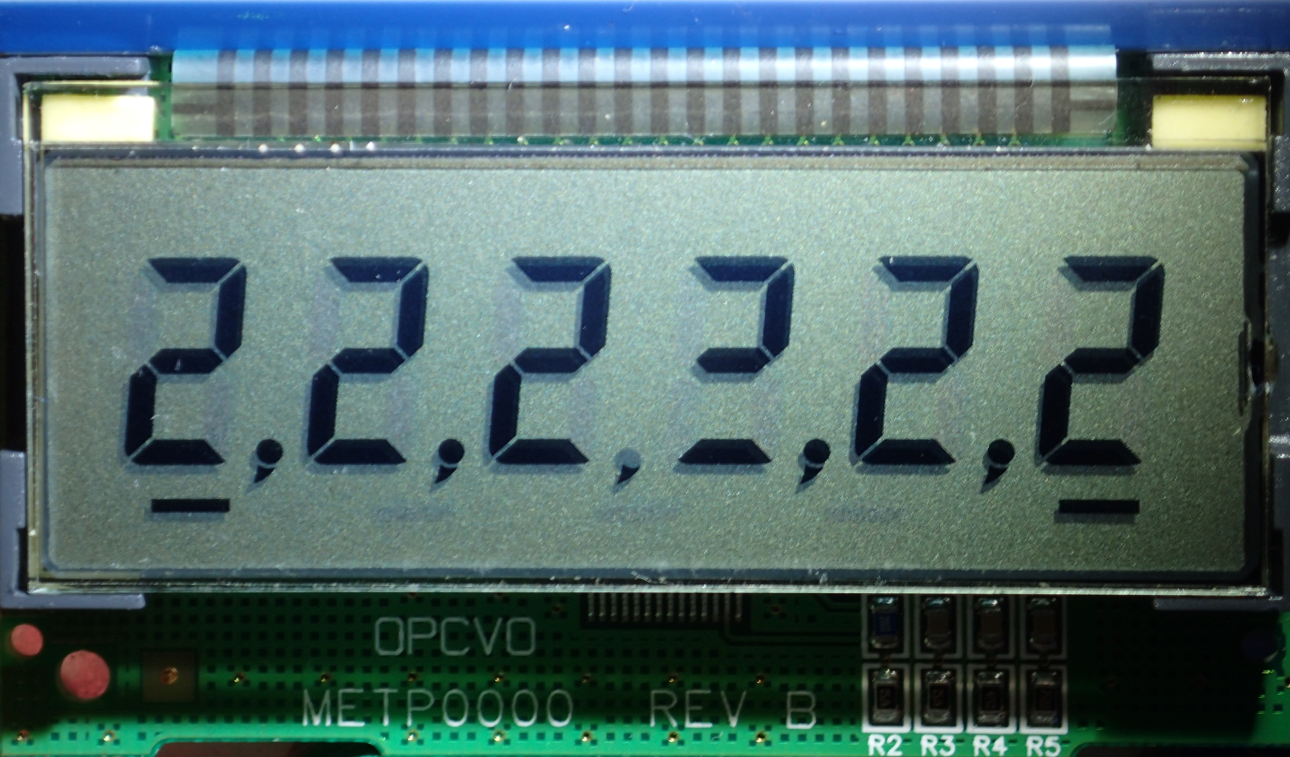
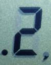 The display is a single line of six digits, the leftmost digit is addressed as digit 0, the rightmost as digit 5. Digits are composed of 9 segments - the usual 7 segments plus decimal point to the left and comma to the right. It initially appears that the display has 10 individual elements to each digit - the seven segments plus decimal point, comma, and an under-bar segment. But it turns out that the under-bars are driven from a variety of otherwise unused digit segments. There are five under-bars, the leftmost one is driven by the first digit's “Decimal point” segment (there is no leading decimal point on the display) . The next three are driven by segments of a phantom 7th digit - a digit that is otherwise not visible. And the last, rightmost, under-bar is driven by the “Comma” segment of the 6th digit (there is no trailing comma on the display).
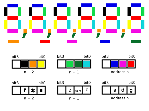 It took me a while to realise that the inbuilt segment decoder on the μPD7225 chip wasn't really much use. The 7-segment decoder couldn't drive all nine segments and an examination of the board revealed that the COM3 output wasn't connected so the 14-segment decoder wasn't being used either. 2)
So it appeared that the only way to address all the segments of each character was to use the command “write-immediate-data”, to write directly into the display memory - three writes of 3-bit words (n to n+2 on the segment layout diagram). Hence my driver does not need to do any “data” writes, everything is a “command” write, the “C/D” control line is not needed.
Details of the module's controller configuration choices : R1 across the cl1/cl2 clock generation pins is 200kΩ - giving nominally an about 120kHz clock. The resistor ladder wired across the Vlc1,2,3 pins is for 1/3 bias. COM3 appears to be unconnected, which implies a divide by 3 time-division type of LCD (using COM0,1,2).
Testing was done with mode byte set to 0x48 (= 1/3 bias method, divide-by-3 time-division drive , and a frequency division ratio of 1/2^7 (frame frequency=fCL /(2^7 × 3)).
Arduino to METP0000 wiring
Electrically the interface is pretty simple, there are four signal lines Busy, SI, SCLK, and CS. Plus C/D, Reset, power and ground. The Reset can be connected via an inverter to the Arduino reset line, or left unconnected (software initialisation of the μPD7225 seems sufficient). Power and ground can be directly connected to the same pins on a 5V Arduino board. As noted above the C/D (command/data) control line is redundant for my driver as all digits are written with “write-immediate-data” commands instead. The Busy line can be dispensed with by using sufficient delays between commands, this driver supports both methods.
The module's interface has an RJ45 socket, so a re-purposed Ethernet cable, cut to length, makes for easy connection. The display is designed to be remote from the controlling processor and has Schmitt trigger buffers on the inputs which will help handle poor signals from a long lead.
The control lines can use any available Arduino digital pins (or even analog ones if needed).
There is no contrast adjustment on this module.
METP0000 library
As mentioned earlier the library is based on a standard Arduino LiquidCrystal.cpp LCD library. I wrote a version (v1.30) with a “write()” function suitable for use with the standard <print.h> routines. This worked fine, but didn't allow for controlling the decimal point - it was unable to set the decimal point as part of a digit. Instead it had to display a blank digit with a decimal point set in the corner. Besides looking strange, that wasted a whole digit space just to display a decimal point, and we don't have a lot of digits to play with.
Character Set
Because driving the 9 segments necessitates bypassing the 7 segment decoder, we are free to create whatever character shapes we wish out of the available segments. To simplify development I used a 16bit word to define each character - 3 nybbles containing 3bits each, plus a fourth nybble that I occasionally used to specify the digit position (as not all digit positions are exactly the same). If I continue to develop this driver, I might truncate this to 8bits per digit, and handle the single bits for the decimal point or comma separately. I initially hand crafted a table of 9-bit alpha-numeric character patterns based on other peoples 7-segment character fonts. I then came across Jose Pino's XLS spreadsheet 3), which I modified for the 9 segments and odd coding required for this display. In my version the results are shown as a 3 digit number suitable to use as the hex character definition in my driver.
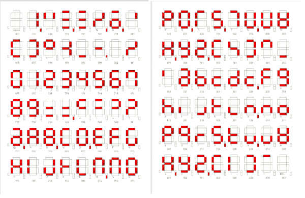 7 Segment design spreadsheet in Excel format, for designing segment layout.
7 Segment design spreadsheet printed to PDF, showing example segment layout.
Design decisions in version 1.1 include going for the best visual appearance and letting your mind decide on the exact character represented, by context. eg an 8 and capital B are the same, M and N are the same, () [] {} are all represented by []. Generally I have added the “comma” tick element to highlight a secondary usage of the same symbol. My thinking is to have a character set that is legible to a wide audience without having to learn a new alphabet. But some symbols are just unintelligible ![]() .
.
I have also made upper and lowercase versions where possible.
There is a repeated group for hex number representation so that I can avoid ambiguities that might arise from my experimentation (there is a separate print routine to handle printing numbers in a base other than 10 - but it hasn't been amended to use this extended character set).
There are 16 locations in the table, from characters, 0 through 15, that I envisage using as programmable character space - but not yet implemented. At the moment the library only supports using ASCII codes from 0x20 to 0x7f.
I suppose the primary use of this type of display will be to provide digital values, perhaps with additional digits representing the units. Another, rare, function might be communicating an error status. Printing messages would be a minor part (no real reason to use this display if your primary interest is in displaying text), so character sets might be optimised for the few words actually needing to be displayed.
Overall I'm not convinced by the results, so still a work in progress.
μPD7225 command set
- MODE SET
- initialise the controller
- SYNCHRONIZED/UNSYNCHRONIZED TRANSFER
- synchronise screen updates with frame rate
- PAUSE TRANSFER
- pause data transfer mid stream for interrupt processing
- BLINKING ON/OFF
- enable or disable blinking data bits
- DISPLAY ON/OFF
- turn whole display on or off
- WITH/WITHOUT SEGMENT DECODER
- use internal 7/14 segment decoders or raw data
- LOAD DATA POINTER
- position cursor for writing to screen and blink memory
- WRITE DATA MEMORY
- write to screen with immediate data
- AND/OR DATA MEMORY
- AND or OR current contents with immediate data
- CLEAR DATA MEMORY
- clear all screen memory
- WRITE BLINKING DATA MEMORY
- specify which segments can blink, using immediate data
- AND/OR BLINKING DATA MEMORY
- AND or OR segment blink data with immediate data
- CLEAR BLINKING DATA MEMORY
- set all segments to not blink
Communications protocol
The Arduino sends command and data words MSB (most significant bit) first through the SI pin, clocked by the SCLK pin. Chip select is asserted, commands and data are sent, chip select it released, the LCD then updates its screen and resets the data address pointer to zero, ready for the next command.
Sigrok analysis of control signals from this library (NB these are from earlier versions, timings have been tweaked since)
Using “Busy” control signal from μPD7225 :
 metp0000-demo-busytest.sr
Using set delays between commands :
 metp0000-demo-nobusytest.sr
In normal operation the μPD7225 would be configured to use the segment decoder, so a display sequence would consist of asserting Chip select (CS), asserting Command/Data (CD) for a command, writing the positioning the data pointer (cursor) command, asserting C/D for data, writing digit codes to the LCD, and de-asserting CS. The digit codes are 8bits, the MSB selecting between the 7 and 14 segment decoders, and then 4 or 7 bits are data for the decoder. For the 7 segment decoder data values from 0 to 9 generate the symbols '0' through '9' on the display. Internally the decoder just stores a sequence of bits into the display memory, corresponding to the segments to be displayed. So after positioning the cursor 6 writes are needed to fill the 6 digit display.
If the decoder is not used, you instead write bits corresponding to the desired segment patterns directly to the display memory. And here the sequence is slightly different as the sets of 3 data bits specifying each segment are part of write-immediate-data-commands (or to look at it another way there are lots of commands, each one specifying a different part of the segment pattern). A sequence of three commands defines the segments displayed at one digit location. So after positioning the cursor 18 writes are needed to fill the 6 digit display. But all of these writes are 'commands', no 'data' writes are needed.
Standard LiquidCrystal library functions implemented
- begin(col,row)
- Initializes the display, usually done once in a sketch's setup() routine.
- (parameters ignored, just here for LiquidCrystal.h compatibility)
- clear(uint8_t start = 0, uint8_t stop = 5);
- Clear the screen of all pixels and home the cursor.
- (nonstandard: optional start and end parameters so can clear a range rather than whole screen)
- home()
- Set the location for next data output (cursor location) to 0,0.
- display(); / noDisplay();
- Turn on or off the display
- setCursor(col, row)
- Set the location for the next character to be displayed.
- (row parameter ignored, just here for LiquidCrystal.h compatibility)
- scrollDisplayLeft()
- Scroll current line one character to the left.
- scrollDisplayRight()
- Scroll current line one character to the right.
Standard LiquidCrystal library functions not yet implemented
- blink(); / noBlink();
- Turn on or off cursor blinking (if cursor visible)
- cursor() / noCursor()
- Show/don't-show cursor, at location ready for next character.
- leftToRight()
- Normal Western language display mode where words are written starting at the left of the display.
- rightToLeft()
- Mode used for Japanese and other languages where characters are written starting at the right of the display.
- autoScroll() / noAutoscroll()
- Automatically scroll/don't-scroll when the cursor (whether visible or not) reaches the far edge of the display.
- createChar()
- Design a user defined character
Custom METP0000 library functions implemented
- flash(bool speed = slow); / noFlash();
- turn on or off blinking of all segments that have blinking enabled
- optional speed parameter: fast/slow
- setFlash(); / unSetFlash();
- enable or disable all segments to blink
- setSegment(uint16_t seg); / clearSegment(uint16_t seg);
- set or clear a set of segments for a particular digit position
- setBar(uint8_t bar); / unSetBar(uint8_t bar);
- set or clear one of the 5 under-bar segments
- print(String);
- print(const char*);
- print(char);
- print(uint32_t, uint8_t base = DEC);
- print(int32_t, uint8_t base = DEC);
- print(uint16_t, uint8_t base = DEC);
- print(int16_t, uint8_t base = DEC);
- print(double, uint8_t decimals = 2);
Custom METP0000 library functions not yet implemented
- customChar(uint16_t);
- may be the same as createChar() when implemented
Implementation notes
All the print() functions are re-inventions of the wheel necessitated by wanting to handle the decimal point segment as an extra character space. That is, when a decimal point or full-stop (period) is printed by these routines, they turn on the appropriate decimal point segment instead of somehow using the whole digit position just for that character. This allows us to print what would otherwise be 7 character strings like “1.23456”, rather than “1 .2345”. This even extends to printing strings like “8.8.8.8.8.8”. But we can't print a leading ”.” or a trailing ”.” without having a blank digit at that first or last location - eg ” .12345” or “12345. ” . This is because there physically isn't a leading or trailing decimal point as part of the display segments.
We could conceivably extent this to the “comma” segment, or accommodate European languages that use a comma ”,” as a decimal signifier rather than ”.” . The comma segment is really just a 'tail' below the decimal point, and it looks better to display the decimal point and comma tail segments to get a good looking comma. But handling commas presents two problems. First, the comma segments are on the opposite side of each digit (see single-digit image in the “Hardware description” section), complicating the logic, especially if you want to display the decimal point simultaneously with the comma to form a more complete looking comma. The second problem is that I use the comma as a small corner “tick” in my alphanumeric characters to hint that this is an alternate use of the same symbol.
I am still contemplating whether it is sensible to drive such a short display as though it is a normal character output device, it might be more useful to have output routines that update the whole display each time, rather than printing a partial line, and keeping track of the cursor.
This is still a work in progress, but further progress might be slow in coming as the METP0000, that I was using, is now barely functional: from the start it had problems - 2 segments on the fourth digit didn't work and the whole display would only operate at all if I put pressure on the flex cable. In trying to fix the missing segments, I made it worse ![]() . I suspect the cable problems were caused by me trying to examine the circuit board beneath the LCD - only so much flexing that flex cables will tolerate. But if I ever get another one … (donations of modules are welcome
. I suspect the cable problems were caused by me trying to examine the circuit board beneath the LCD - only so much flexing that flex cables will tolerate. But if I ever get another one … (donations of modules are welcome ![]() ).
).
The programs (v1.50):
- helloworld5.ino, sketch to test the LCD library
- fourdigitdemo2.ino, sketch to test the LCD library
- metp0000_lib.h, METP0000 library
- metp0000_lib.cpp, METP0000 library
intermediate version (v1.30) that uses print.h libraries
- metp0000_lib-printh.h, METP0000 library
- metp0000_lib-printh.cpp, METP0000 library
References and Additional Resources
- Datasheet for the μPD7225, May 2002 upd7225_2002-05.pdf
- Datasheet for the μPD7225, 1990 upd7225.pdf
- Application note for the μPD7225 upd7225_ap_note.pdf.
Other Arduino LCD drivers
- KS0073 SPI LCD, LCD display panel Arduino driver
- Canon MX300, Canon MX300/310 printer LCD display panel Arduino driver.
- NEC µPD7228 and μPD16434 LCD display panels Arduino driver
- SPI LCD, LCD display panel Arduino driver
- Toshiba T6A34 LCD display panel Arduino driver
If any referenced page no longer exists, try looking for its URL on http://archive.org.
