| LCD Description | |
|---|---|
| Model | Diymore 3310 |
| Manufacturer | Diymore |
| Recovered from | |
| Board IDs | LPH7779, SKU:030028BA, A22-19-A-03 |
| LCD type | positive |
| Polarizer type | transflective |
| Columns | 84 pixels |
| Rows | 48 pixels |
| Char matrix | - |
| Driver IC | Philips PCD8544 |
| Backlight | blue LED, or white LED |
| Arduino driver | U8g2lib.h |
| Connector | pins |
| Num Pins | 8 |
| Pin spacing | 0.044” |
| Module size | 45L x 45W x 6.5H mm |
Optimal contrast value : 63 - 70 (0x3f - 0x46)

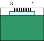
Connector layout, LCD front view
| LCD pinout 1) | ||
|---|---|---|
| Pin | Label | Description |
| 1 | VDD | 2.7V - 3.3V |
| 2 | CLK | Clock |
| 3 | SDIN | Data in |
| 4 | D/C | Data or command |
| 5 | SCE | Chip select |
| 6 | VSS | Ground |
| 7 | VLCD | DC/DC voltage converter2) |
| 8 | RES | Reset |
| PCB Connector pin-out | Arduino test rig | |||
|---|---|---|---|---|
| Pin# | Label | Description | Pin | colour |
| 1 | RST | Reset | 8 | Grey |
| 2 | CS | Chip Select | 10 | Yellow |
| 3 | D/C | Data/Command | 9 | Purple |
| 4 | DIn | Serial Data Line | 11 | Blue |
| 5 | Clk | Serial Clock | 13 | Green |
| 6 | Vdd | 2.7V to 3.3V | ||
| 7 | LED | Backlight Control | ||
| 8 | GND | Power Ground | ||
Additional info
Driver libraries
- Library: Adafruit GFX Graphics Library
-
- pcdtest.ino
- ( Logo, graphics, scale & rotated text, falling stars)
- InterlinkKnight Display_LCD_Nokia_5110_SPI_PCD8544_U8GLIB.ino
- (hello world with shapes and left/right justified numbers)
- Library: LCD5110_Graph
- (Text and graphics demo with pacman)
- Library: Nokia 5110 LCD library
- Library: Universal 8bit Graphics Library
- GraphicsTest.ino
- (Graphics and pages of fonts)
Applications
Notes
There are two common Nokia phone LCD modules regularly for sale. Most commonly described as Nokia 5110 boards, some are infact designed for the Nokia 3310 LCD. The two modules are functionally the same, but have slightly different wiring as one module uses a 9 pin LCD (LPH7366, Nokia 5110) and the other an 8 pin LCD (LPH7779, Nokia 3310).
The Diymore modules appear to use recycled LCDs (I have seen minute tell-tail signs of blue corrosion material as the result of expired batteries, around the electrical contacts).
The Philips PCD8544 controller uses an SPI like protocol, but can't share the bus with other devices.
Each byte written is a column of 8 bits, columns are written out from left to right, then top to bottom. The first byte represents the top, left column of 8 bits. The second represents the one to the right of it, and so on. The least significant bit is the top of the column, and then following pixels proceed downward to the most significant bit. But note that the driver libraries probably use an entirely different byte layout for bit-mapped images.
The cheaper PCB mounts for these displays have only 4 backlight LEDs compared to 6 on some phones, and the LEDs are mounted facing up, rather than sideways, horizontally across the board, so don't spread light very evenly.


