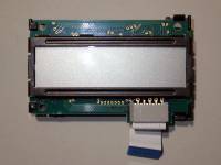
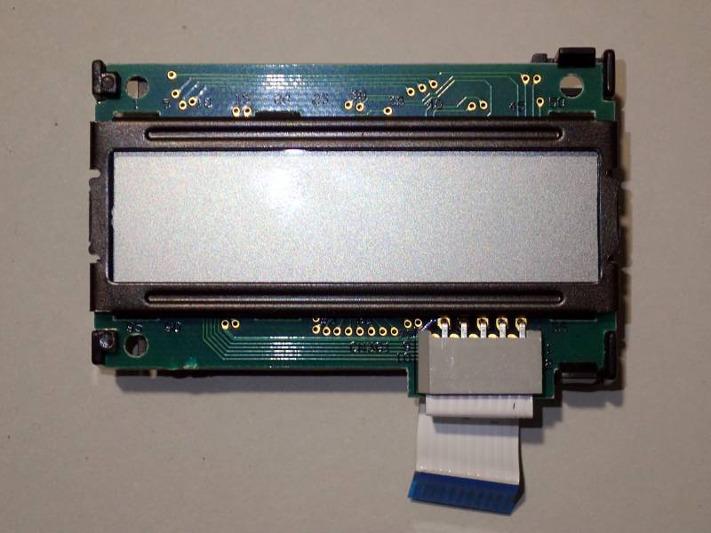
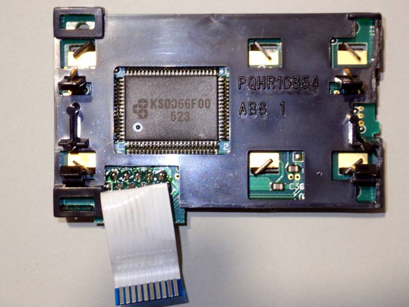
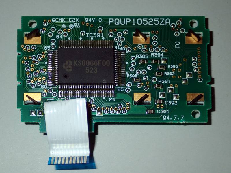
| LCD Description | |
|---|---|
| Model | PQUP10525ZA |
| Manufacturer | |
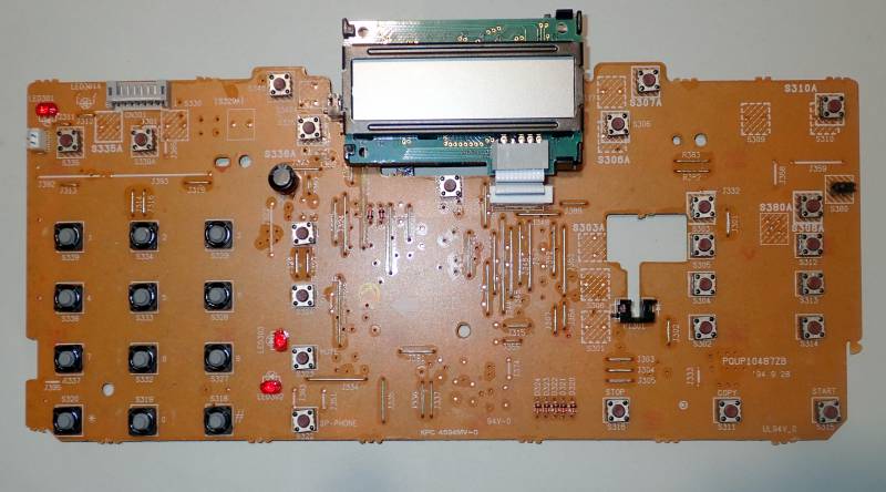
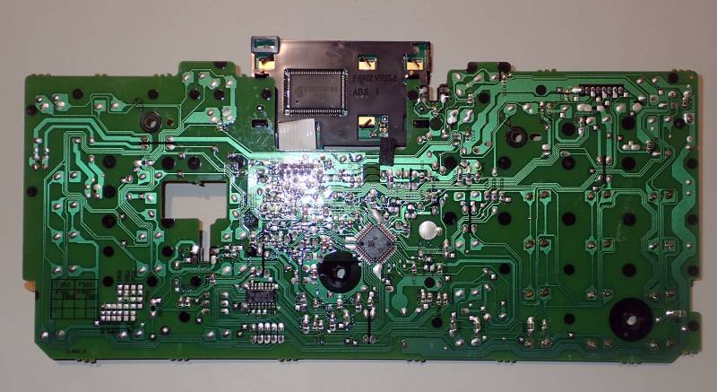
| Recovered from | Panasonic KX-F2750NZ Fax |
| LCD type | positive |
| Polarizer type | reflective |
| Columns | 15 |
| Rows | 1+ |
| Char matrix | 5×7 |
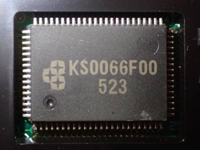
| Driver IC | KS0066F000 |
| Backlight | - |
| Arduino driver | LiquidCrystal.h |
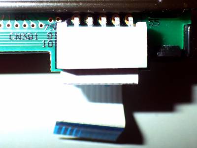
| Connector | PCB flex cable |
| Num Pins | 10 |
| Pin spacing | 0.05” |
| Connector pin-out | Arduino test rig 1) | |||
|---|---|---|---|---|
| Pin# | IC pin | Label | Pin | colour |
| 1 | RS | rs | 8 | grey |
| 2 | R/W | r/w | gnd | black |
| 3 | E | e | 9 | purple |
| 4 | DB4 | d4 | 4 | blue |
| 5 | DB5 | d5 | 5 | green |
| 6 | DB6 | d6 | 6 | yellow |
| 7 | DB7 | d7 | 7 | orange |
| 8 | GND | gnd | gnd | brown |
| 9 | Vcc | +5V | +5V | white |
| 10 | V5 | v5 | pot | black |
Structured as 8 chars * 2 rows except that both logical rows are displayed inline on the first line. The 16th logical character position doesn't display a normal character but instead displays icons on the 2nd line, some of which are arrows that are normally used to point to labels on the LCD surround (see below for how to drive these icons).
Datasheets
- PQUP10525ZA schematics:
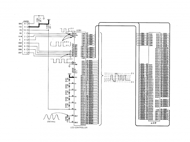
This schematic diagram is from the KX-F1000 service manual 2). Not a particularly similar FAX machine, but it does have the same LCD holder part number, PQHR10354, and online photos show a similar display, implying it uses a similar LCD, so the pin-out might be the same (confirmed through testing).
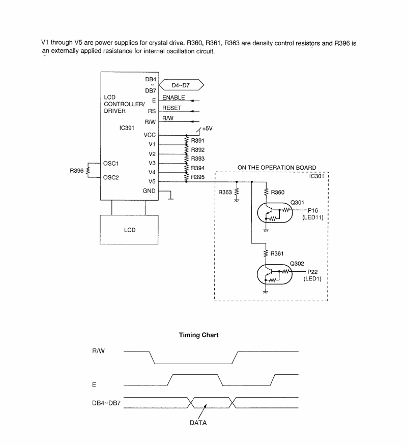
Schematic from similar FAX, KX-F2200 3).
Examples :
The second line of symbols is controlled by individual pixels in the 5×7 character written to the 16th screen location (column 8, row 2). Below are the character matrix binary codes corresponding to each display element on that second line. Only pixels on the 1st, 6th and 7th matrix rows are significant, you could either dynamically create a programmable character to write to the control location, or just select characters that have suitable pixels in their matrix from a table.
| 1 | 2 | 3 | 1 | 2 | 3 | v | v | v | v | v | v |
|
|
|
|
|
|
|
|
|
|
|
|
