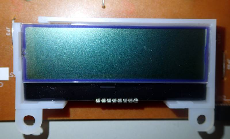
| LCD Description |
| Model | MDP12BS17-SR-T |
| Manufacturer | |
| Recovered from | Epson WF-2530 1) |
| Board IDs | 2142717-01, 2142716 00 |
| LCD type | positive |
| Polarizer type | reflective |
| Columns | 128 pixels |
| Rows | 28 pixels |
| Char matrix | 3×14 to 8×14 2) |
| Driver IC | ST7567 (CoG) 3) |
| Backlight | - |
| Arduino driver | |
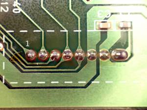
| Connector | pins |
| Num Pins | 8 |
| Pin spacing | 0.07” |
| LCD1 Pinout | Arduino test rig 4) |
| Pin# | IC Label | Funtion | Connected to | Measured | Pin | colour |
| 1 | CSB | Chip Select | (cn1 pin 8) | 3.38V | | |
| 2 | RSTB | Reset | (74VHC595 pin 4 (Qe)) | 3.38V | | |
| 3 | A0 | Register select | (cn1 pin6, 74VHC595 pin 14 (SER data input) via 100Ω) | 0V | | |
| 4 | SCLK | Clock | (cn1 pin5 via 220Ω), (74VHC595 pin 11 (clock) via 220Ω), (74VHC165 pin 2 (clock) via 220Ω) 250kHz or 3MHz | 0V | | |
| 5 | SDA | Data In | (cn1 pin2), (74VHC165 pin 9 (QH) via 3.3k) | 3.38V | | |
| 6 | VDD | Power | 3.38V, bypass capacitor to GND | | | |
| 7 | VSS | Ground | oV | | | |
| 8 | VG | LCD power | capacitor to GND | 6.94V | | |
| JK33149A, 2142717-01 Board, CN1 pinout | Arduino test rig 5) |
| Pin# | Label | Connected to | Pin | colour |
| 1 | | Buzzer- | | |
| 2 | SDA | (lcd pin5) | | |
| 3 | GND | | | |
| 4 | Vcc | | | |
| 5 | CLK | (lcd pin4 via 220Ω), (74VHC595 pin 11 (clock) via 220Ω), (74VHC165 pin 2 (clock) via 220Ω) | | |
| 6 | RS | (lcd pin3 via 100Ω) | | |
| 7 | | (74VHC595 pin 13 (output enable)) | | |
| 8 | CS | (lcd pin1) | | |
| 9 | | (74VHC165 pin 1 (parallel load)) | | |
| 10 | | SW1 (closes to gnd) (power button) | | |
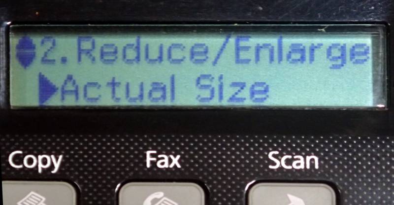
“2 line bitmap LCD” Approximately 20 characters by 2 rows.
IC1, 74VHC165 (8bit parallel line/serial out shift register) is used for serializing the keyswitch selections,
IC2. 74VHC595 (8-Bit Shift Register with Output Latches) is used for decoding serial data to latched outputs to turn on status LEDs (Power, Wifi, ADF) and one LCD control line (chip select)
IC1 & IC2 can use power supplies of 2V to 5.5V, LCD 3.3V powered?
Datasheets
Examples :


