Published 20 Feb 2021
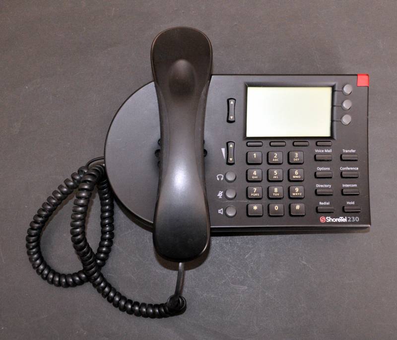
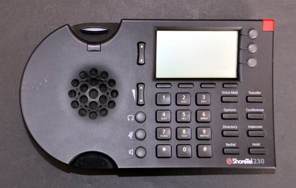
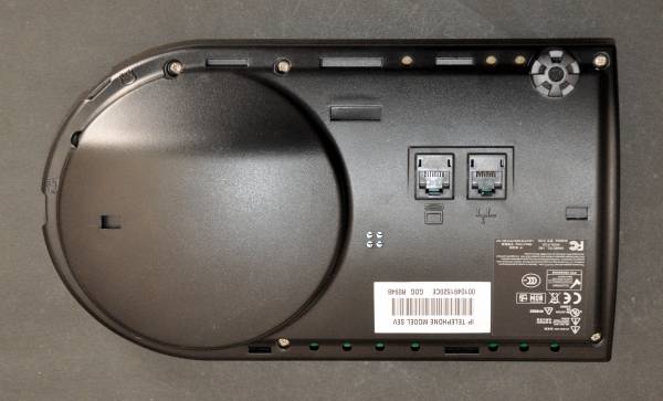
Shoretel IP 230
Overview
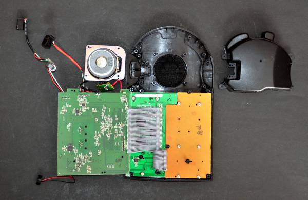
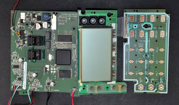
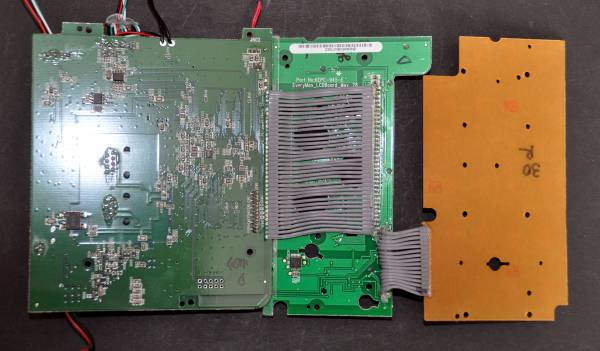
Shoretel IP 230 PABX IP phone.
Hardware description
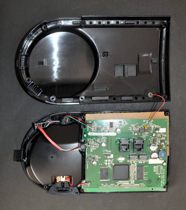
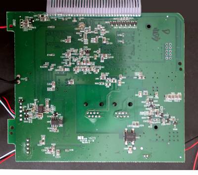
The phone can be powered from 33V to 48V across the bridge rectifier (D601) outputs. But note that the +ve terminal of the bridge rectifier is the ground level for the logic power supply, so if powering this directly the supply needs to be isolated. Tested with Ubiquiti 48V 0.5A +(4,5)pins, -(7,8)pins network power supply, phone plugged into PDE socket.
Diagnostics
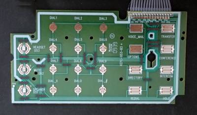
The are a number of built in test/setup functions obtained by pressing mute (microphone with a line through it) then a series of numbers representing the function names:
- dial
3424#(DIAG) - dial
4636#(INFO) - dial
7464#(PING) - dial
73738#(RESET) - dial
772667#(RRAMOS), factory reset,- at the prompt dial
1234#as password, to enter “KPD Mode” - dial
25327#(CLEAR)
- dial
73887#(SETUP)
Keys need to be pressed solidly as sometimes they don't register.
Components
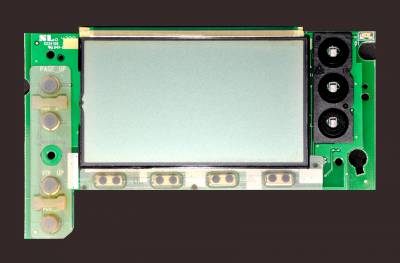
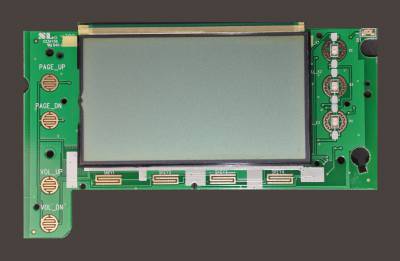
- LCD 5 rows of 27 alphanumeric characters (described as 141 pixels by 44 pixels). Not a straight-forward character LCD display, some character locations 6 pixels wide, plus extra dividing lines.
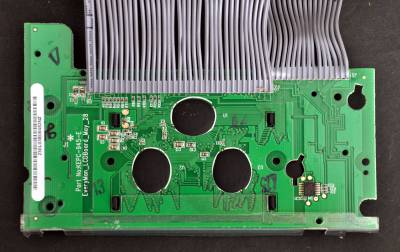
- 74HCT164N 8 bit shift register, serial in, parallel out, on the LCD board
- EM96AB L4871 8 pin
- EH13A 1 A Low Dropout Positive Voltage Regulator, 3 pin
- YD 34119 Low Power Audio Amplifier, 6 pin dip
- AZ324M-E1 919R34 14 pin dip
- 96AQ N01A 3 terminal voltage regulator
- 5001A1 97M AYCP 6 pin dip
- FL4310 934P 3 terminal voltage regulator
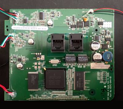
- Broadcom BCM1113KPBG Network Controller & Processor ICs IP Phone Chip
- Spansion S29AL032D90 32 Megabit CMOS 3.0 Volt-only Flash Memory
- Samsung K4S641632N-LC60 SDRAM 64M-Bit 4Mx16 3.3V
- YD V358 AXL1Y
- AP34063 650mA DC-to-DC converter
Startup sequence
On powerup D2 to D4 light up green then after 2 seconds they go out and D1 flashes red.
Ten seconds after powerup D1, D2, D3, D4, D53 (headset), D52 (mute), D51 (speaker) flash in sequence.
One second later the LCD is powered up, then displays “No Ethernet” (if it is not connected at this point)
