Published 13 Jun 2021
DEC H-500 Computer Lab
Overview
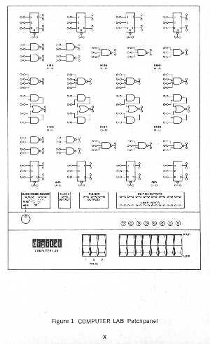
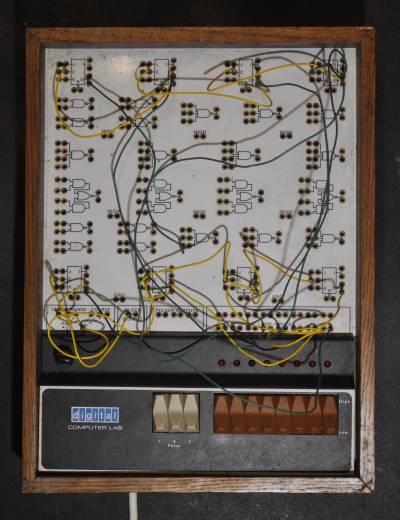
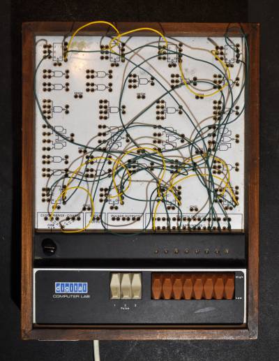
To help train electrical engineers in digital electronics Digital Equipment Corporation (DEC) produced a digital logic trainer together with a training course. It allows students to connect up various configurations of basic logic gates following a workbook to get a hands on idea of what it was all about.
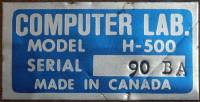
There is a 110V version (H-500) and a 240V version (H-500-A), but all the logic runs on 5V. It came with a Computer Lab workbook (item B-350) and an assortment of 107 patch cords of assorted lengths from 2.75” to 24.75” (item “916”). There was also a Computer Lab Teaching Wall Poster (24” x 36”).
Hardware description
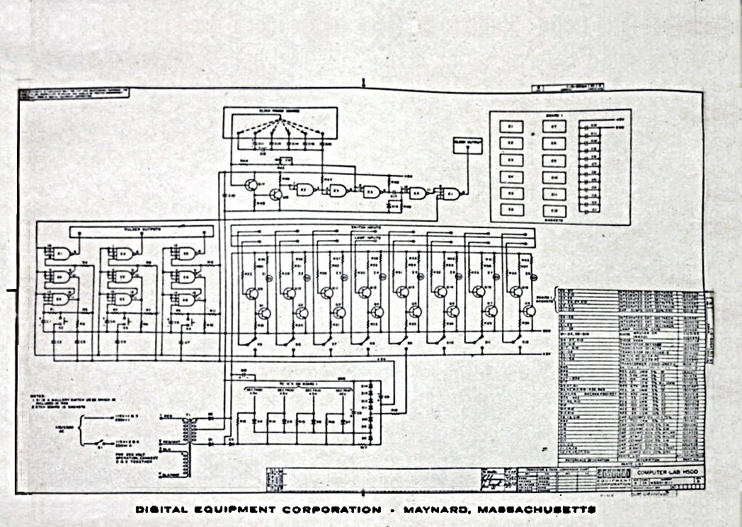
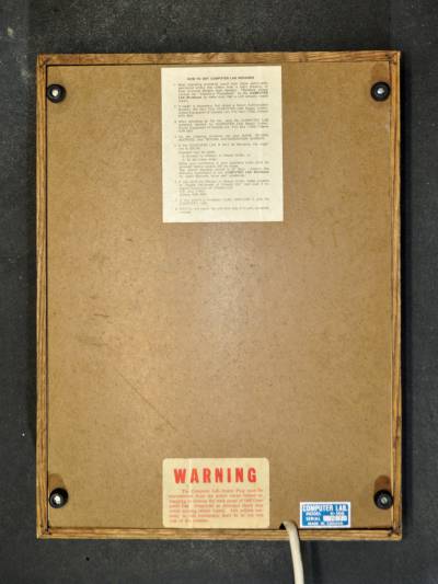
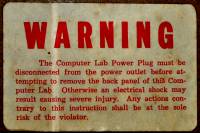
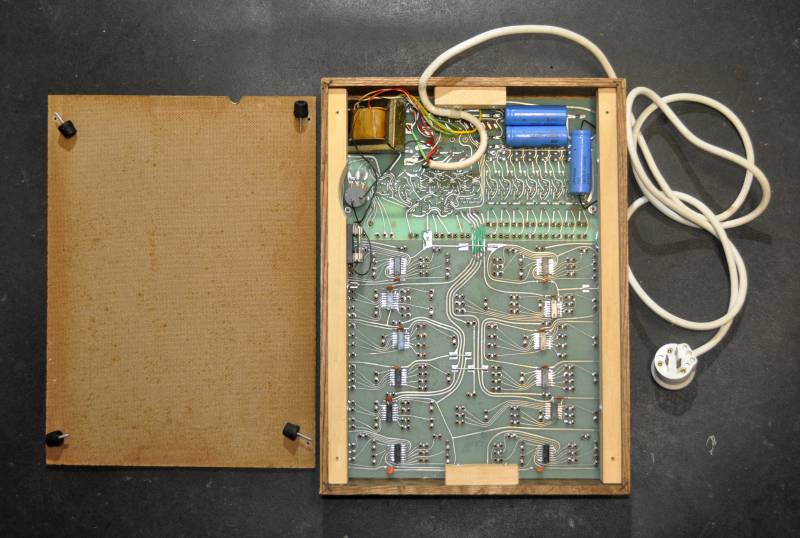
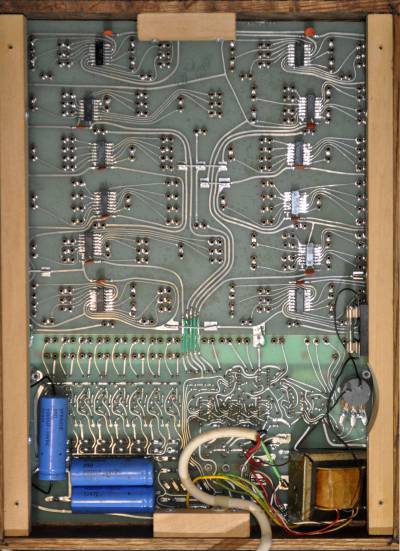
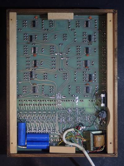
The logic gates are provided by 12 TTL logic chips: 7473, 7400, 7420, 7450, 7400, 7473, 7473, 7410, 7420, 7450, 7410, 7473. The chips are mounted on the under side of a PCB (item H500 PATCHCORD PANEL5004577 5404576B). There is a separate PCB containing the input switches, output lights, oscillator, and power supply (BEWARE mains voltages are present on this board).
There are 8 rocker switches for providing logic 0 or 1 inputs, and 3 momentary rocker switches to provide pulsed inputs. Additionally there is also a variable resistor control for an oscillator that has 6 selectable clock ranges, 3 “fine” and 3 “coarse”
The patch cords are colour coded according to length:

| Colour | Length | Quantity |
|---|---|---|
| Brown | 2.75” | 20 |
| Red | 4.75” | 30 |
| Orange | 6.75” | 25 |
| Yellow | 8.75” | 20 |
| Green | 16.75” | 10 |
| Blue | 24.75” | 2 |
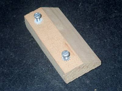
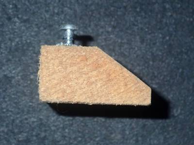
And they have uncommon tapered pins crimped onto each end:
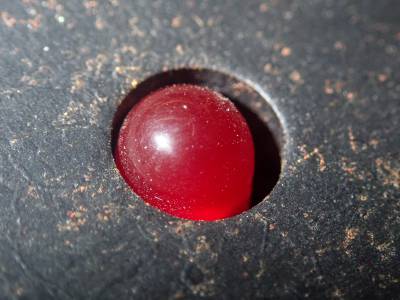
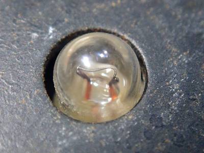
I've got two versions, one with light bulbs as output, the other with red LEDs. I'm not entirely sure whether the LEDs were a standard version, or whether someone has retrofitted them (possibly to replace failing light bulbs).
- DEC H-500 schematic:
Examples
References and Additional Resources
- H-500 Computer Lab Workbook copy 2
If any referenced page no longer exists, try looking for its URL on http://archive.org.

