{{:pilone.png |Page under construction (Cone icon by Fornax, CC-BY-SA 3.0, wikimedia commons)}} ((PAGE UNDER CONSTRUCTION))

Published 16 Jul 2021

2D Plotter

\\ ===== Overview ===== As my first foray into the world of computer numerical control (CNC) machines, I thought I would build a 2D plotter from recycled CD/DVD drives. There are seemingly endless examples of these machines on the internet, some with quite detailed construction instructions (for a few examples see [[:electronic:recycle:cdrom|cdrom recycling]]). We might also call this style of device a "2D printer", or "CNC plotter", but I'll stick to "2D plotter". In case it is not obvious what this device is, a plotter of this sort uses a pen to draw on a piece of paper. The machine either moves the pen or moves the paper or both. It needs an external source (eg a computer) to send it commands of what lines to draw - the computer converts images, diagrams, or even text, into a series of line drawing pen movement commands. As a practical device, a plotter of this size and accuracy has limited real application, but building one certainly entails getting to grips with the fundamental concepts involved in CNC machines. And the same techniques can be used to construct a number of different CNC devices from laser engravers to 3D printers. My objective is to construct this without using bought parts but instead maximising the usage of recycled hardware components. I expect the only new materials used would be glue, though I prefer to use screws rather than glue anyway. I could potentially use recycled h-bridge driver chips from the CD/DVD drives, but initially I intend to use an Arduino and new h-bridge drivers as the electronics. Software needed consists of three parts. - Code (eg //Grbl// ((https://github.com/grbl/grbl/wiki))) to run in the plotter's embedded controller (in this case an Arduino), that interprets drawing commands (eg //G-code// ((https://en.wikipedia.org/wiki/G-code))) and moves the pen using motors to draw lines. - Code (eg //UGS// ((https://winder.github.io/ugs_website/guide/platform/))) to run on your PC/Mac etc, to send files containing drawing commands to the plotter. - Code (eg //Inkscape// ((https://inkscape.org/))) to run on your PC/Mac etc, to convert images into files containing drawing commands.
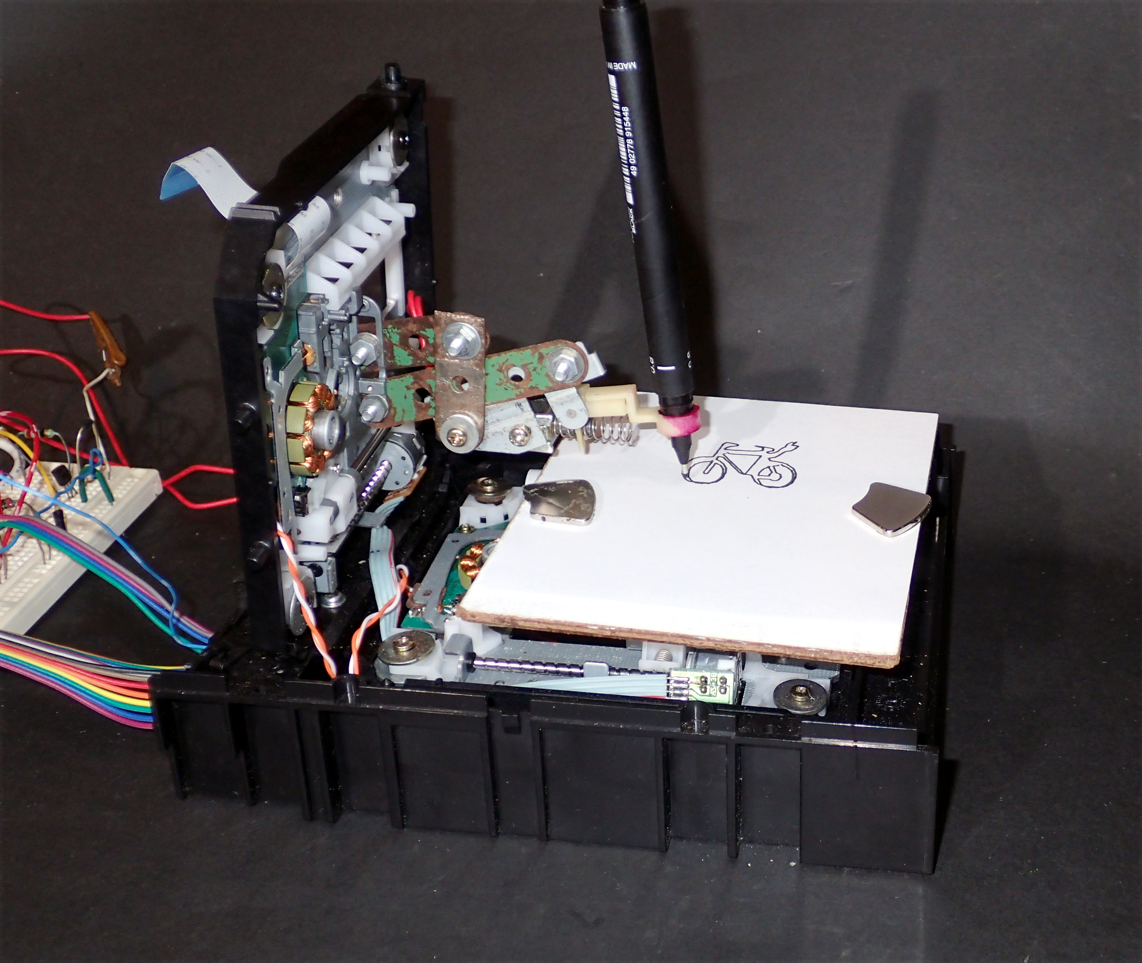
Completed 2D Plotter at work.
((Plotted image from https://commons.wikimedia.org/wiki/File:Sinnbild_E-Bikes.svg, by Mediatus - interpretation of drawing from the German Federal Minister for Transport and Digital Infrastructure)) \\ ===== Design options ===== The CD/DVD drive laser LED carriage assembly (sled) provides a ready-made motor-driven axis. So two CD/DVD drives can provide two independent axes. Somehow these need to be arranged to move a drawing platform in two directions, or a pen in one direction and the platform in the other, or leave the platform stationary and move the pen in two directions. The pen also needs to be raised and lowered, and this is perhaps the aspect that needs the most work creating a custom mechanism. The pen mechanism could be another CD/DVD sled, a linear motor, or a servo. |{{:arduino:2dplotter:insert_image_here.png?400|X and Y axis move platform}} |{{:arduino:2dplotter:insert_image_here.png?400|X-axis move platform, Y-axis move pen}} |{{:arduino:2dplotter:insert_image_here.png?400|X and Y axis move pen}} There seem to be three alternative motor types used in CD/DVD sleds; stepper motor, brushless motor with rotary encoder, and linear motor. Most commonly mini CNC projects use the stepper motor version of these sleds, probably because all can be driven with the same readily available hardware (H-bridge drivers). The other alternative motor types require further work determining the exact driver requirements. |{{:arduino:2dplotter:insert_image_here.png?400|stepper driven sled}} |{{:arduino:2dplotter:insert_image_here.png?400|brushless motor driven sled}} |{{:arduino:2dplotter:insert_image_here.png?400|linear driven sled}} ===== Design considerations ===== The sleds are not designed to carry much weight, so configurations such as mounting one sled on the carriage of the other would be quite hard on the mechanism, though may work depending on the exact sled design. A common configuration is to have the sleds mounted at right angles in an "L" shape, the horizontal sled moving the drawing platform along an X-axis, and the vertical sled moving the pen along a Y-axis (and also holding the pen up/down mechanism). Again the weight of the pen raising mechanism needs to be minimal as it extends away from the sled and puts strain on the carriage. To draw things accurately the mechanism needs to be reasonably rigid so that we can get repeatable positioning of the plotter pen. CD/DVD drives are usually mounted on rubber buffers, but replacing them with washers seems appropriate to get rigidity. There is some play in lead screw positioners, so exact positioning may depend upon the direction of carriage travel, if this proves to be a problem I suppose that I could program it to always approach from the same direction when positioning (eg overshoot the position then move back from the other direction). The platform needs to be level and at right angles to the Y-axis so that the pen makes consistent contact with the drawing surface. Likewise, the pen needs to contact the surface at right angles so that we are not digging in when moving in one direction, then dragging the pen tip when moving back. It is useful to have limit switches at the end of each axis so that the mechanism isn't damaged by over-runs, although CD/DVD mechanisms seem to be designed not to self destruct and are quite tolerant of this. Having limit switches on at least one end of the X and Y axes is useful for homing the mechanism on startup as the pen may be left in an unknown position from a previous job. I thought it might be useful to have a stepper motor controller that could do micro-stepping to improve resolution, but a quick calculation shows each normal step moves about 0.15 mm, less than one-fifth of the width of the pen tip being used (0.8 mm), and the 'slop' in the pen holding mechanism turns out to be rather larger than this too. A fibre tip pen produces nice drawings, but how the pen is delivered to the page needs to be considered. With a solenoid activated pen loading mechanism, that slams the pen onto the page, the fibre tip gets compressed and distorted - as an example the 0.8mm pen tip that I was experimenting with, ended up about 1.2mm wide. ---- ======Construction ====== =====X and Y Axis===== I have a number of old CD/DVD drives and chose to use [[:electronic:equipment:cdrom:gd8000|Hitachi GD-8000]] drives as I had two of them, which allows me to have identical mechanisms for the X and Y axes. |{{electronic:equipment:cdrom:p6218976c.jpg?400x300|GD-8000 overview}}| These drives have a mini stepper motor that drives the sled through a lead screw. The sled has a travel of about 37mm and a limit switch at one end. |{{arduino:2dplotter:p7139112c.jpg?400|GD-8000 stepper motor, sled and limit switch}}|{{arduino:2dplotter:p7139108a.jpg?400|Limit switch}}| I did not want to use additional materials to construct a frame to hold the sleds, so re-used the plastic chassis parts from the GD-8000 drives. |{{:arduino:2dplotter:p7129100a.jpg?400|GD-8000 inner and outer plastic chassis}}| |{{:arduino:2dplotter:p7139101a.jpg?400|One and a half GD-8000 chassis, mounted at right angles}}|{{:arduino:2dplotter:p7139103b.jpg?400|Screws securing the chassis members together}}| The sled assemblies were disassembled and reassembled with inflexible mounts. Wires were attached to the limit switches. |{{arduino:2dplotter:p7139106a.jpg?400|Partially disassembled sled}}|{{arduino:2dplotter:p7139112d.jpg?400|Sled with new mountings and wires to limit switch.}}| The horizontal sled forms the X-axis, and needs to be fixed in a level position and moves from front to back. The vertical sled is fixed at 90° to the base to form the Y-axis, and moves from side to side. {{:arduino:2dplotter:p7139113a.jpg?800|Two sleds mounted at right angles to form X and Y axes}} ===== Attaching the Arduino===== The X and Y stepper motors each have four wires, their limit switches have two wires each. The limit switches are normally open ("NO" contacts) and need to provide a low signal (0 V) when the carriage reaches it's furthest travel and closes the switch. So one side of each switch is connected to a ground line (GND), and the other is brought out to a connector to attach the Arduino. Continuing with the recycling theme, I used a 34 pin "IDE" to edge connector adapter from an old 5¼" floppy disk drive. This has two rows of 17 pins, the bottom row are usually all connected together and grounded, but in this application they can be ignored. The top 17 are sufficient for connecting our two axes and a pen raising mechanism (yet to be designed!). The PCB edge connector is easy to solder wires to. |{{:arduino:2dplotter:p7259149a.jpg?400|IDE to PCB edge connector adapter}}| |{{:arduino:2dplotter:p7139118a.jpg?400|Drive mount guide}}|{{:arduino:2dplotter:p7139119a.jpg?400|Guide cut down to use as brace}}| |{{:arduino:2dplotter:p7139116a.jpg?400|Chassis, sled, brace and PCB to IDE adapter, before assembly}}| |{{:arduino:2dplotter:p7139121a.jpg?400|Connector mounted on GD-8000 chassis}}|{{:arduino:2dplotter:p7139122a.jpg?400|Connector mounted on GD-8000 chassis}}| |{{:arduino:2dplotter:p7139124a.jpg?400|Mounted PCB edge connector}}|{{:arduino:2dplotter:p7139126a.jpg?400|Stepper motor wires soldered to PCB edge connector}}| The wiring to the PCB to IDE adapter (used as a connector) is fairly arbitrary, simply determined here by the length of the pre-wired stepper motor cables: ^ IDE pin ^ Connection | |2|spare| |4|Z limit switch| |6|Y limit switch| |8|X limit switch| |10|Limit switch common (GND)| |12|Z axis phase-b| |14|Z axis phase-b| |16|Z axis phase-a| |18|Z axis phase-a| |20|Y axis phase-b| |22|Y axis phase-b| |24|Y axis phase-a| |26|Y axis phase-a| |28|X axis phase-b| |30|X axis phase-b| |32|X axis phase-a| |34|X axis phase-a| Although I experimented with a number of Arduino //G-code// interpreters, I standardised on using the default //Grbl// Arduino pin assignments so that I didn't have to rewire things between experiments. ^ Pin ^ Connection ^ Description | |2|x_step|Step Y axis| |3|y_step|Step Y axis| |4|z_step|Step Z axis| |5|x_dir|X step direction| |6|y_dir|Y step direction| |7|z_dir|Z step direction| |8|step_disable|Disable steppers (power down steppers)| |9|x_limit|X limit switch reached| |10|y_limit|Y limit switch reached| |12|z_limit|Z limit switch reached| //Grbl// assumes the axis steppers are driven by an H-bridge stepper driver chip, if we want to drive them more directly (pulsing the two-phase windings in software) we will have to modify the code or user an alternative //G-code// interpreter (we might do this if we want to use some recycled electronics rather than new H-bridge drivers). {{:arduino:2dplotter:insert_image_here.png?400|Arduino to plotter wiring.}}
Testing X and Y axis mechanisms (single stepping motors).
=====Drawing platform===== The drawing platform is fixed to DVD drive's old laser mount on the horizontal sled, and the plotting pen will be attached to the laser mount on the vertical sled. A simple platform was made from scraps of wood then screwed to the former laser LED holder on the X-axis sled. |{{arduino:2dplotter:p7179146a.jpg?400|Parts for wood platform}}|{{arduino:2dplotter:p7179145a.jpg?400|Assembled wooden platform (view from underneath).}}| ===== Drawing pen ===== ====Fixed pen holder==== For testing purposes, a temporary fixed (no raising mechanism) pen holder was constructed from Meccano pieces: {{:arduino:2dplotter:p7265837a.jpg?200|Temporary fixed pen holder overview.}} |{{:arduino:2dplotter:p7265838a.jpg?200|Temporary fixed pen holder above.}}| |{{:arduino:2dplotter:p7265836a.jpg?200|Temporary fixed pen holder side.}}| {{arduino:2dplotter:p7215800a.jpg?800|2D Plotter with temporary fixed pen holder.}} \\ \\ \\
Test sketch on 2D Plotter (fixed pen).
{{arduino:2dplotter:p7215796a.jpg?200|2D Plotter test output.}} ====Pen moving mechanism==== As expected, construction of a pen raising/lowering mechanism requires a bit of work. We need something fairly light as it must be carried by the lower Y-axis CD sled and it extends out across the plotter bed so exerts leverage on the sled too. The Arduino controller firmware expects to have stepper motors on all three axes, so that seemed to be the first choice for the pen lower/raise mechanism (effectively the Z-axis of this plotter). I looked at using a lightweight CD sled from a laptop DVD drive - it has a very small (ie lightweight) stepper motor and a lightweight frame to hold it. But in trying to connect leads to the motor I broke one of the phase winding connections, so decided it was too fiddly to persevere with. A look through my recycled collection of motors and solenoids found a couple of possibilities. One is a stepper from a 3.5" floppy disk drive, and the other is a [[:electronic:actuator:servo:tds05c|'sent' page marker]] from an old fax machine (used to stamp an 'X' on documents that pass through it to signify that they have been transmitted). The latter mechanism seems to be the simplest to physically mount, and already has a sort of pen holder attached. {{electronic:actuator:servo:p8230200a.jpg?400|fax marker mechanism}} The mounting bracket needs to be flattened out, because in its original purpose it was mounted at an angle to the paper, and I need it to be at right angles. I adapted the mounting of the solenoid on the bracket and added a couple of old Meccano pieces to allow me to secure it to the Y-axis laser mount assembly. I would have preferred to use the solenoid to lift the pen and allow gravity and/or a spring to return it to the page, but the design of the pen holder make this impractical. So a spring is used to raise the pen and the solenoid to lower it, which makes the pen's contact with the paper dependent on the exact positioning of the mechanism (if a spring was used it would automatically compensate for unevenness/unlevelness of the plotter bed, and the pressure on the pen tip could be adjusted easily. The solenoid tends to slam the pen tip against the paper, which is not good for a fibre pen tip. Also we can end up with the pen not reaching the page, or dragging quite noticeably, if the height isn't quite right). |{{arduino:2dplotter:p8250254a.jpg?400|2D Plotter pen mechanism side.}}| |{{arduino:2dplotter:p8250257a.jpg?400|2D Plotter pen mechanism top.}}| |{{arduino:2dplotter:p8250251a.jpg?400|2D Plotter pen mechanism side.}}| |{{arduino:2dplotter:p8250256a.jpg?400|2D Plotter pen mechanism bottom.}}| The solenoid needs to have a buffer/driver as the Arduino cannot supply enough current to drive it and it also protects the Arduino output. There are many possible ways to drive this, but a simple recycled transistor does the job, The component values are not critical, and a wide range of NPN transistors will work in this circuit (the transistor used here(([[https://pdf1.alldatasheet.com/datasheet-pdf/view/247023/RENESAS/2SD655ETZ-E.html|2SD665]])) is just what was to hand, not chosen for any particular characteristic. For more info on this sort of circuit see [[http://www.ee.ic.ac.uk/pcheung/teaching/de1_ee/Project/How%20to%20drive%20a%20solenoid.pdf|How to drive a solenoid]], and [[https://www.eeeguide.com/transistor-buffer-circuit/|transistor buffer circuit]]) : {{arduino:2dplotter:solenoid_driver_schem.png?300|2D Plotter pen solenoid driver.}} |{{arduino:2dplotter:p8230186a.jpg?400|2D Plotter pen top.}}| |{{arduino:2dplotter:p8230185a.jpg?400|2D Plotter pen side.}}| {{arduino:2dplotter:p8230190a.jpg?400|2D Plotter pen front.}}
2D Plotter with solenoid
2D Plotter with solenoid driven pen lowering mechanism
---- ====== Software and firmware ====== The plotter hardware needs some way to receive instructions of what to draw, and turn those into plotter movements. //G-code// is often used as the instruction set, and //Grbl// software running on an Arduino is often used to interpret those instructions and convert them to movement of the plotter. The G-code interpreter software for the Arduino is burnt into its erasable memory so is considered to be firmware. The plotter could be designed to just print a limited range of images stored in its memory, and could then be a stand-alone device (hmmm, that's an idea - for demonstration purposes, it could have a few embedded sets of G-code). Or if it had some removable memory attached (eg an SD memory card) it could print from there. Or it could receive sets of G-code commands via USB (or a network connection if it had ethernet or wifi). Traditionally this sort of minimal plotter is set up to receive G-code commands from a 'sender' program ===== Firmware ===== //Grbl// has many clever features and takes up most of the resources of an Arduino Uno, there are other G-code interpreters like //Mini_CNC_Arduino_Plotter// (simpler) and //Not_grbl// (simpler and faster). As this is a learning exercise, I thought I'd try out //Grbl//, even though it is a bit of overkill for such minimal hardware. This software runs on Arduino UNO compatible boards with an ATmega328P processor (and has no doubt been ported to others). It can be downloaded as an Arduino IDE sketch and installed by compiling the //grblUpload// sketch from the examples folder. In the simpler G-code interpreters the configuration settings/parameters, for the particular hardware in use, are hardcoded into the program - so it needs to be recompiled and downloaded to change anything. //Grbl//'s settings and parameters can be set by sending commands, either via a serial console, or sender program. The command **//''$$''//** lists the available settings. This is what I ended up with: $0=100 (Step Pulse Length, μsec) $1=25 (Step Idle Delay, msec) $2=0 (Step Pulse Configuration) $3=1 (Axis Direction) $4=0 $5=0 $6=0 $10=31 $11=0.010 $12=0.002 $13=0 $20=0 (Soft Limits, Enable/Disable) $21=0 (Hard Limits, Enable/Disable) $22=0 (Homing Cycle, Enable/Disable) $23=3 $24=50.000 $25=50.000 $26=250 $27=1.000 $30=1000 $31=0 $32=0 $100=6.000 (X steps/mm) $101=6.000 (Y steps/mm) $102=6.000 (Z steps/mm) $110=500.000 (X - Max Rate, mm/min) $111=500.000 (Y - Max Rate, mm/min) $112=500.000 (Z - Max Rate, mm/min) $120=10.000 (X - Max Acceleration, mm/sec²) $121=10.000 (Y - Max Acceleration, mm/sec²) $122=10.000 (Z - Max Acceleration, mm/sec²) $130=36.000 (X - Max Travel, mm) $131=36.000 (Y - Max Travel, mm) $132=36.000 (Z - Max Travel, mm) I had expected that the physical movement of the pen would be the limiting factor as far as speed was concerned, but it turns out that many g-code commands are sent to draw relatively simple objects, especially curves which are implemented as many short straight strokes. Of the firmware that I tried out //Not_grbl// was by far the fastest, but the code was more difficult to modify than other simpler g-code interpreter software/firmware. I needed to modify the firmware to implement driving my pen up/down hardware, and it was convenient to have it implement a fuller set of g-code, to minimise the number of edits required to run a variety of g-code files (eg examples found on the internet and g-code produced by Inkscape extensions). One interesting fact emerged, there are different interpretations/implementations of the time parameter of the pause/dwell command "G4 Pxxx". Some use the parameter to specify the delay in milliseconds, others use it to mean a delay in seconds! eg the command //G4 P180// will cause some g-code interpreters to dwell for 3 minutes, whereas others will take it to mean dwell for 180 milliseconds. I am inclined to implement it as a delay in seconds when the parameter is specified with a decimal point (eg //G4 P0.500//) and interpret it as milliseconds when specified as an integer (eg //G4 P500//). ===== Sender software ===== We can communicate with the //Grbl// software on the plotter's Arduino controller through the Arduino IDE serial console, but for non-trivial drawing, we need something that can send complete lists of instructions - a 'sender' program such as //bCNC// or //UGS//. One problem that I had was finding "sender" software that would communicate reliably with the Arduino firmware. The communication protocol seems pretty simple (though I haven't found a definition of it anywhere) - but basically, for each command sent to the Arduino, it is expected to reply with a response of 'ok'. I am not clear whether non G-code commands and comment lines are meant to be responded to. I suspect some of the problem was just losing 'ok' responses from the Arduino (perhaps caused by electrical noise from the motors). Also some Arduinos use XON/XOFF flow control commands on the serial link (ie allowing the receiver to tell the sender to start and stop), while others ignore them. {{arduino:2dplotter:p8310258a.jpg?800|2D Plotter example output.}}((Examples:\\ Spur_gear (PD by //inductiveload//, [[https://en.wikipedia.org/wiki/File:Spur_Gear_12mm,_18t.svg|Spur Gear 12mm, 18t]])\\ Reuse (CCBYSA by //Tony//, [[http://projects.scorchingbay.nz|My Projects]])\\ Gear (PD trivial, [[https://File:Wikipedia_interwiki_section_gear_icon.svg|Interwiki gear]])\\ Sheep-outline (PD? - can't find original source)\\ Tux_Mono (CCBYSA //Larry Ewing//, [[https://commons.wikimedia.org/wiki/File:Tux_Mono.svg|Tux Mono by Iwan Gabovitch]])\\ Penguin-outline (CC BY 4.0, [[https://svg-clipart.com/color/ScDgKbY-penguin-outline-clipart|ScDgKbY penguin outline]])\\ Finnish_bike (PD //Finnish Transport Agency//, [[https://commons.wikimedia.org/wiki/File:Finnish_bike_symbol.svg|Finnish bike symbol]])\\ Swellow (PD?, [[https://web.archive.org/web/20150428174110im_/http://www.disegnidacoloraregratis.it/foto/thumb/cartoni/pokemon2/pokemon_swellow.JPG|Swellow]])\\ Sinnbild_E-Bikes (PD //German Government//, [[https://commons.wikimedia.org/wiki/File:Sinnbild_E-Bikes.svg|Sinnbild E-Bikes]]) )) \\ ====== Conclusions ====== =====Redesign Considerations ===== It would have been more useful to have the limit switches detect the zer0 location on each axis, rather than the limit of travel, as the most common requirement, is to home the carriages back to the origin (0,0) as you might not be entirely sure where the carriages end up after a plot run, especially while still debugging software/firmware! Of course if the hardware isn't forgiving when you hit the end-stops (ie it does physical damage), you need limit switches at both ends of each axis. One aspect that I thought was caused by a fault, was that the stepper motors heated up alarmingly when stopped , I've subsequently realised this is caused by the driver powering the motor windings to hold the carriage in position, which isn't necessary if you are not micro stepping as the motor rests at individual steps quite well (and there is not a lot of force trying to pull it out of position). So the motor can be powered down when plotting is paused or stopped. \\ ---- ====== References and Additional Resources ====== * [[http://wiki.linuxcnc.org/cgi-bin/wiki.pl|LinuxCNC]] Knowledge Base. * **G-code** * [[https://wiki.shapeoko.com/index.php/G-Code|G-code]] reference. * [[http://wiki.linuxcnc.org/cgi-bin/wiki.pl?CoordinateSystems|G-code]] coordinate systems. * [[http://www.diymachining.com/downloads/GRBL_Settings_Pocket_Guide_Rev_B.pdf|G-code]] pocket guide. * [[https://bengler.no/grbl|Grbl home]] the original author, Simen Svale Skogsrud, explains what, why and how. * [[https://github.com/grbl/grbl/wiki/Frequently-Asked-Questions|Grbl FAQ]] * [[https://github.com/gnea/grbl/wiki|Grbl Wiki]] * [[https://github.com/gnea/grbl|Grbl github]] * [[http://edutechwiki.unige.ch/en/Grbl|Grbl]] Edutech page. * [[https://github.com/grbl/grbl/wiki/Interfacing-with-Grbl|GRBL interface]] * Mini_CNC_Arduino_Plotter code * Not_grbl code * **G-code sender software** * [[https://winder.github.io/ugs_website/|UGS]] Universal G-code Sender, Java code. * [[https://github.com/winder/Universal-G-Code-Sender|UGS github]] * [[https://github.com/vlachoudis/bCNC|bCNC]] G-code Sender, Python code. * [[https://wiki.shapeoko.com/index.php/BCNC|bCNC]] supporting documentation. * [[https://github.com/bborncr/gcodesender.py|gcodesender.py]] basic G-code sender, Python code. * https://web.archive.org/web/20190623183745/http://zapmaker.org/projects/grbl-controller-3-0/ * **G-code editing software** * [[https://www.scorchworks.com/Gcoderipper/gcoderipper.html|G-Code Ripper]] - Read, probe, split, wrap, scale and rotate G-Code.

If any referenced page no longer exists, try looking for its URL on http://archive.org.

\\ ----
 [[:start|Home Page]]   [[:about|About this Site]]   [[:copyright|Copyright Questions]]   [[:contact|Contact Us]]
\\ \\